
Page 401 - Design and Operation of Heat Exchangers and their Networks
P. 401
384 Design and operation of heat exchangers and their networks
The elements of A and B are given as follows:
ij
ψ
a ijðÞ,q ¼ p ijðÞ,q + p i +1, jð Þ,q
_
C ij
δ ijðÞ,q sC f, ij U f, ij
sC ij + 1 η f, ij +2ψ ij ð q ¼ 1, 2, …, MÞ
_ sC f, ij + U f , ij
C ij
(7.307)
2
_
ψ ij 1 e U p, ij + e U f , ij ^ η f , ij C ij
e
p
p
b ðÞ,q ¼ e ðÞ,q +e ð i +1, jÞ,q + 4 ^ ^ U p, ij + ^ U f , ij ^ η f , ij
ij
ij
_
_
_
C ij 2C ij C ij
1 3
e U f , ij ^ U f , ij
s 7
+ U f , ij η f , ij ^ η f , ij 5 ^p ðÞ,q + ^ ðÞ, i +1, qÞ 2δ ðÞ,q
p
ij
ij
ij
ð
sC f , ij + U f , ij ^ U f , ij
ð q ¼ 1, 2, …, MÞ
(7.308)
The solution of Eq. (7.306) is given by Eq. (7.173).
Example 7.3 Dynamic responses of four-stream plate-fin heat
exchanger.
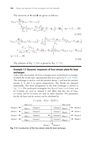
Take a four-stream plate-fin heat exchanger made of aluminum as example,
of which the steady-state experimental data were given by Li et al. (1992).
The exchanger is used to cool the product stream 1 and heat the product
streams 2, 3, and 4 to given temperatures. The blocks are arranged
sequentially. The fluid arrangement in the heat exchanger is shown in
Fig. 7.13. The perforated rectangular fins (h f ¼4.7mm, s f ¼4.2mm, and
δ f ¼0.6mm) are used in channel 6 and offset strip fins (h f ¼4.7mm,
s f ¼2mm, and δ f ¼0.3mm) are used in other channels. The parameters
for the ith layer and jth section can be calculated by
ð
ð
C ¼ ρch f δ f Þ s f δ f ÞW=s f
Plate 5 (1) Plate 10 (6)
Stream 2 Channel 4 Channel 8 Stream 2
Plate 4 Plate 9
Stream 1 Channel 3 Channel 7 Stream 1
Plate 3 Plate 8
Stream 3 Channel 2 Channel 6 Stream 4
Plate 2 Plate 7
Stream 1 Channel 1 Channel 5 Stream 1
Plate 1 Plate 6
Stream 3 Stream 4
Fig. 7.13 Construction of the four-stream plate-fin heat exchanger.