
Page 398 - Design and Operation of Heat Exchangers and their Networks
P. 398
Dynamic analysis of heat exchangers and their networks 381
and eigenvectors of A in Eq. (7.283). The excess plate temperature
distribution in the Laplace domain can be obtained from Eq. (7.282).
This equation gives the general analytical form of the exit temperature
responses of the streams to the inlet temperature disturbances in the Laplace
domain.
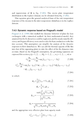
7.4.5 Dynamic response based on Pingaud’s model
Pingaud et al. (1989) first studied the dynamic behavior of plate-fin heat
exchangers with a numerical method. In their mathematical model, they
assumedthatthefindynamicscouldbeneglected,andthesteady-statefineffi-
ciency and bypass efficiency were used to take the heat conduction in the fins
into account. This assumption can simplify the analysis of the dynamic
responses to flow disturbances. We can add the thermal capacity of the fins
into that of the separating plates to take the effect of the fin dynamics into
account. Based on the Pingaud’s assumption, the governing equations are
expressed for section q (q¼1, 2, …, M p ; i¼1, 2, …, n; j¼1, 2, …, m)as
∂t ij _ ∂t ij
C ij + C ij ¼ ψ t p, ij + t p,i +1, j 2t ij (7.289)
ij
∂τ ∂x
C ∗ ∂t p, ij ¼ ψ t ij t p, ij + ψ
ij
p, ij ij i 1, j t i 1, j t p, ij + ϕ t p,i +1, j t p, ij
∂τ
+ ϕ i 1, j t p,i 1, j t p, ij
(7.290)
in which
1
ψ ¼ U p, ij + U f , ij η f, ij (7.291)
ij
2
1
ϕ ¼ U f, ij μ f, ij (7.292)
ij
2
q ffiffiffiffiffiffiffiffiffiffiffiffiffiffiffiffiffi
1
tanh U f, ij =K ij
2
η ¼ (7.293)
f, ij 1 q ffiffiffiffiffiffiffiffiffiffiffiffiffiffiffiffiffi
U f, ij =K ij
2
2
ij
μ ¼ q ffiffiffiffiffiffiffiffiffiffiffiffiffiffiffiffiffi q ffiffiffiffiffiffiffiffiffiffiffiffiffiffiffiffiffi (7.294)
U f , ij =K ij sinh U f, ij =K ij
and the appropriate new effective plate heat capacity reads
C ∗ p, ij ¼ C p, ij + 1 C f, ij + C f ,i 1, j (7.295)
2