
Page 304 - Design of Reinforced Masonry Structures
P. 304
5.24 CHAPTER FIVE
Provide /8-in.-diameter lateral ties at 16 in. on center to match coursing. Code
3
requires top and bottom ties to be within one-half of required spacing at top and bottom.
This would require a tie spacing of 8 in. Provide the top and bottom tie at 8 in. to match
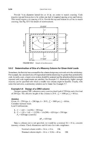
coursing. See Fig. E5.5 for details of reinforcement.
23.625''
Y
3''
8#9
15.625'' #3@16'' 9.625''
3''
Y
3'' 17.625'' 3''
FIGURE E5.5 Details of reinforcement.
5.6.2 Determination of Size of a Masonry Column for Given Axial Loads
Sometimes, the first trial size assumed for the column design may not work out to be satisfactory.
For example, the calculated area of longitudinal reinforcement may be greater than permitted by
code. In such a case, a larger cross section should be assumed and the aforedescribed procedure
repeated until code requirements are satisfied. See Example 5.5. Alternatively, higher strength
masonry can be specified with which a smaller size column might be feasible. Usually, with
some trial and error, a satisfactory solution can be found. See Example 5.7.
Example 5.6 Design of a CMU column
Design a square CMU column to carry a service dead load of 250 kips and a live load
of 200 kips. The effective height of the column is 20 ft. ′ f = 1800 psi, f = 60 ksi.
m y
Solution
Given: D = 250 kips, L = 200 kips, h = 20 ft, ′ f = 1800 psi, f = 60 ksi.
m y
Calculate factored loads.
Load Combinations:
1. U = 1.4D = 1.4(250) = 350 kips
2. U = 1.2D + 1.6L = 1.2(250) + 1.6(200) = 620 kips > 350 kips
P = 620 kips (controls)
u
fP = 620 kips
n
Since a column size is not specified, we would try a nominal 16 × 16 in. concrete
masonry column. Check dimensions and h/t ratio for code compliance.
Nominal column width = 16 in. > 8 in. OK
Nominal column depth = 16 in. < 3(16) = 48 in. OK