Page 308 - Design of Reinforced Masonry Structures
P. 308

5.28                       CHAPTER FIVE

                                                  2
           Calculate fP  assuming  ′ f  = 2000 psi, and A  = 9.0 in.  (Grade 60).
                                           st
                    n
                             m
                             φ
                                .
                              [
                           .
                                           )
                                                ]
                     φP = 080 080  f ′( A −  A +  f A C  P
                       n
                                              y
                                                st
                                          st
                                   m
                                      n
                                             −
                                                              )
                           .
                         = 080 09))[ .080 ( . )(244 90  +  ( . )]( .0937
                               .
                                      20
                                               . ) 6090
                             (
                         =  618kipps
                                     The calculated fP  = 618 kips is just a little less than
                                                 n
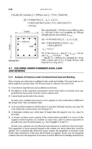
                     15.625"         P = 620 kips. If this is not acceptable, try 2500-psi
                                      u
                                     strength masonry and calculate A st, reqd .
                                                      ′
                                                )
                                                                  ]
                                             .
                                     φP = 09080 080  f A −  A +  f A C
                                                  .
                                                      (
                                          .(
                                                 [
                                                             )
                                       n             m  n   st  y  st  P
                    #3@16 in.
                                     620 = 0.98(0.80)[0.80 (2.5)(244 – A )
                                                               st
          15.625"         12#8           + (60)(A )](0.937)
                                                st
                                               2
                                       A  = 7.43 in.
                                       st
                                                                         2
                                                           2
                                     Try 12 No. 8 bars, A  = 8.64 in.  > A st, ,reqd  = 7.43 in.
                                                   st
                                                      2
                                     and < A st,, max  = 9.76 in.   OK
                                       Specify  ′ f  = 2500 psi for a nominal 16 × 16 in.
                                              m
         FIGURE E5.7                 CMU column and 12 No. 8 Grade 60 bars with
                                     #3ties@16 in. (Fig. E5.7).
         5.7  COLUMNS UNDER COMBINED AXIAL LOAD
         AND BENDING
         5.7.1  Analysis of Columns under Combined Axial load and Bending
         Most columns are subjected to combined loads: axial and bending. The axial loads on col-
         umns result from gravity loads. The flexural loads on columns can result from
         1. Construction imperfections and accidental eccentricity.
         2. Eccentricity of the supported concentrated vertical load (such as reactions from sup-
           ported beams being away from the vertical column axis).
         3. Lateral loads transferred to the column.
           In some cases, columns may possess excess capacity to carry axial loads in addition to
         the design loads. This can happen when

         1. Code-prescribed minimum reinforcement is provided although masonry can carry the
           load without the reinforcement. See Example 5.9.
         2. A minimum column size, which may be larger than the required size (A ), must be
                                                                 n
           provided.
         3. A column can have excess capacity if the reinforcement provided is in excess of that
           required (reinforcing bars are available in certain sizes, and it is almost impossible to
           provide exact area of reinforcement, A ). See Examples 5.8 and 5.9.
                                       st
           In such cases, columns can carry flexural loads (moments) in addition to the axial loads.
         The magnitudes of these moments depend on the column axis about which they would be
         applied. For a symmetrically reinforced square column, the magnitude of moment would
         be the same irrespective of the axes about which it is applied. In the case of rectangular
         columns, however, the magnitude of moments would be different for bending about the two
   303   304   305   306   307   308   309   310   311   312   313