Page 311 - Design of Reinforced Masonry Structures
P. 311

COLUMNS                          5.31

           However, a minimum area of reinforcement must be provided to comply with the code
           requirements.
                         A st, min  = 0.0025 A  = 0.0025 (558) = 1.4 in. 2
                                      n
                                               2
             Provide four No. 6 Grade 60 bars, A  = 1.77 in. . Calculate fP  from Eq. (5.12) with
                                       st
                                                          n
                    2
           A  = 1.77 in. .
            st
                                     ′
                                      (
                                                  ]
                                            )
                      φP =  φ(.080 )[.080  f A −  A +  f A C
                        n            m  n  st  y  st  P
                         = 0.9(0.80)[0.80 (1.8)(558 – 1.77) + (60)(1.77)](0.937)
                         = 612 kips > P  = 400 kips
                                    u
             b. Moment capacity:
             The column has an excess axial load capacity of 612−400 = 212 kips. Therefore, it can
           resist some bending moment. Because the column square, it is symmetrical about both
           axes so it would resist the same moment about either axis. As a result of bending, two
           No. 6 bars along one face of the column would be in compression, and the other two bars
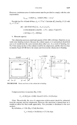
           in tension. Figure E5.8B shows the strains and forces in the column due to bending.
                                          e m = 0.0025
                 23.625''                            0.80 f’ m

                                             e′ s               3''  a
                                                             C s     2
                                                  a =                  C m
                     4#6            C
                               3''
                #3@12 in.         23.625''     NA                    d –  a
                               3''                                      2


                                         s
                                        e ≥ e y         T = A s f y
                3''    3''
         FIGURE E5.8B  Strains and forces in the column due to bending.


             Compression force in masonry [Eq. (4.6)]:

                              ′
                                                     .
                     C = 0 80.  f ab = 0 80 1 8.  ( . )( a 23 625)(  .  ) = 34 02 akips
                       m
                             m
             (Note: Theoretically, the area of compression reinforcement should be subtracted
           from the masonry area in compression. However, this precision is ignored here as it
           would not affect the final result appreciably. This procedure is discussed in the next
           section).
             By definition, a = 0.8c [Eq. (4.5a)]; therefore,
                          C  = 34.02a = 34.02(0.8c) = 27.216c kips
                           m
   306   307   308   309   310   311   312   313   314   315   316