
Page 313 - Design of Reinforced Masonry Structures
P. 313
COLUMNS 5.33
P u = 400 k
M n
11.8125'' 11.8125''
5.8765''
C s = 50.9 k
T = 52.8 k C m = 403.8 k
3'' 8.8125'' 8.8125'' 3''
C L
FIGURE E5-8D
Equilibrium is satisfied; all forces acting on the column include those due to bend-
ing are shown in Fig. E5.8D. The compression force in masonry C acts at d/2−a/2 =
m
½(23.625 – 11.82) = 5.9 in. from the centroidal axis of the column. Forces C and T act
s
at 3 in. from the opposite faces of the column. Take moments of all forces about the
centroidal axis of column:
M = 52.8(8.8125) + 402 (5.9) + 50.8(8.8125)
n
= 3284.78 k- in = 273.73 k-ft
fM = (0.9)(273.73) = 246.4 k-ft
n
The column can support a bending moment of 247.83 k-ft in addition to an axial load
of 400 kips. It is noted that because the column cross section is square, it can resist a
bending moment of 246.4 k-ft about either axes.
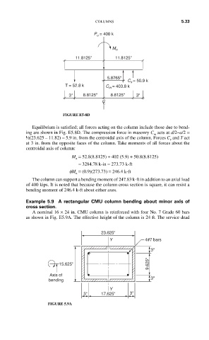
Example 5.9 A rectangular CMU column bending about minor axis of
cross section.
A nominal 16 × 24 in. CMU column is reinforced with four No. 7 Grade 60 bars
as shown in Fig. E5.9A. The effective height of the column is 24 ft. The service dead
23.625''
Y 4#7 bars
3''
15.625'' 9.625''
Axis of
bending 3''
Y
3'' 17.625'' 3''
FIGURE 5.9A