
Page 318 - Design of Reinforced Masonry Structures
P. 318
5.38 CHAPTER FIVE
By definition, a = 0.8c [Eq. (4.5a)], therefore,
C = 31.25a = 31.25(0.8c) = 25c kips
m
Force in compression steel is calculated from strain (ε′) in it, which is calculated based
s
on strain distribution diagram (Fig. E5.11B).
′ ε c − 3
s =
ε m c
c
− 3
ε ′ = ( ) ε
s m
c
From Hooke’s law, the stress in steel reinforcement ′ f is
s
( ) ( ) ( )
c
− 3
− 3
− 3
c
c
f ′= ′Eε = ε E = (. ) ( , = kips
0 0025 29 000) = 72 5.
s s s m s
c c c
Area of two No. 6 bars in compression, ′ A = 1.20 in. 2
s
Force in compression bars,
⎡ ( ) ⎤ ( )
c − 3
c − 3
)
.
A f
C = ′′= (.120 725 = 87 kipps
s s s ⎣ ⎢ c ⎦ ⎥ c
The force in two No. 6 bars in tension (assuming yielding) is
T = A f = 1.20(60) = 72.0 kips
s y
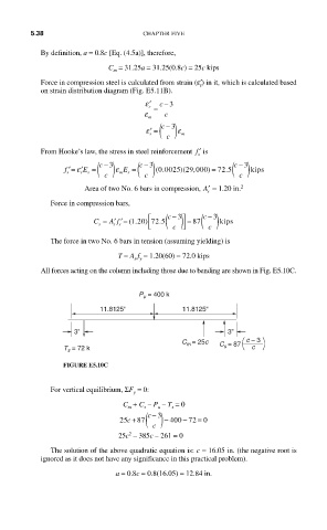
All forces acting on the column including those due to bending are shown in Fig. E5.10C.
P u = 400 k
11.8125'' 11.8125''
3'' 3''
C m = 25c C = 87 c – 3
T s = 72 k s c
FIGURE E5.10C
For vertical equilibrium, ΣF = 0:
y
C + C – P – T = 0
m s u s
c −
3
=
25c + 87 ( ) − 400 72 0
−
c
2
25c – 385c – 261 = 0
The solution of the above quadratic equation is: c = 16.05 in. (the negative root is
ignored as it does not have any significance in this practical problem).
a = 0.8c = 0.8(16.05) = 12.84 in.