
Page 320 - Design of Reinforced Masonry Structures
P. 320
5.40 CHAPTER FIVE
of the column when both forces are acting simultaneously. A column can resist a nominal axial
load fP when there is no moment acting on the column (pure axial case). Similarly, it can resist
n
a bending moment fM (pure flexural case) when there is no axial load present. In between these
n
two values (fP and fM ), a column can resist combinations of axial loads and bending moments
n
n
such that the magnitude of each force is less than its corresponding nominal value. For a given
axial load (P < fP ), a column can resist a bending moment M such that M < fM . Obviously,
n
n
there can be many such combinations of these two forces depending on their magnitudes. The
interaction diagram is a plot of many such points, each of which represents a unique combination
of P (on y-axis) and M (on x-axis), which a column can resist simultaneously.
First some fundamentals for plotting an interaction diagram. The axial strength of a
column depends on the compressive strength of masonry, cross-sectional dimensions, area
and yield strength of longitudinal reinforcement, and the h/r ratio. Therefore, each column
would have a unique interaction diagram based on the unique values of these parameters.
The flexural strength of a column depends also on the same parameters that control its axial
strength (except the h/r ratio), but it is also influenced by the configuration of longitudinal
reinforcement. Positions of longitudinal bars in the cross section influence the position of
neural axis, depending on their distance from the face of the masonry.
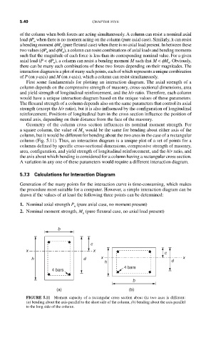
Geometry of the column cross section influences its nominal moment strength. For
a square column, the value of M would be the same for bending about either axis of the
n
column, but it would be different for bending about the two axes in the case of a rectangular
column (Fig. 5.11). Thus, an interaction diagram is a unique plot of a set of points for a
columns defined by specific cross-sectional dimensions, compressive strength of masonry,
area, configuration, and yield strength of longitudinal reinforcement, and the h/r ratio, and
the axis about which bending is considered for a column having a rectangular cross section.
A variation in any one of these parameters would require a different interaction diagram.
5.7.3 Calculations for Interaction Diagram
Generation of the many points for the interaction curve is time-consuming, which makes
the procedure most suitable for a computer. However, a simple interaction diagram can be
drawn if the values of at least the following three points can be determined:
1. Nominal axial strength P (pure axial case, no moment present)
n
2. Nominal moment strength, M (pure flexural case, no axial load present)
n
b
c
x x c
h d x x
h d
4 bars
4 bars
b
(a) (b)
FIGURE 5.11 Moment capacity of a rectangular cross section about the two axes is different:
(a) bending about the axis parallel to the short side of the column, (b) bending about the axis parallel
to the long side of the column.