
Page 319 - Design of Reinforced Masonry Structures
P. 319
COLUMNS 5.39
The values of C and C can now be calculated from the calculated value of c. Thus,
s
m
the forces acting on the column are
C = 25c = 25(16.05) = 401.25 kips
m
s ( ) ( 16 05 − 3 )
.
c − 3
C = 87 = 87 = 70 74 kips
.
.
c 16 05
Check equilibrium: ΣF = 0:
y
C + C – P – T = 401.25 + 70.74 – 400 – 72 = − 0.01 kips ≈ 0 (rounding off error)
m
s
u
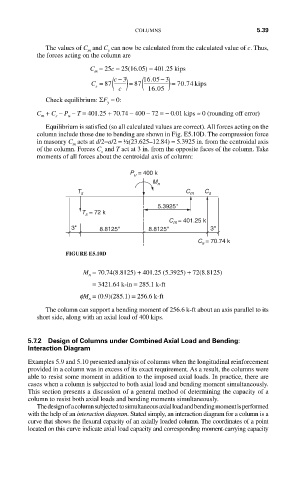
Equilibrium is satisfied (so all calculated values are correct). All forces acting on the
column include those due to bending are shown in Fig. E5.10D. The compression force
in masonry C acts at d/2−a/2 = ½(23.625–12.84) = 5.3925 in. from the centroidal axis
m
of the column. Forces C and T act at 3 in. from the opposite faces of the column. Take
s
moments of all forces about the centroidal axis of column:
P u = 400 k
M n
T s C m C s
5.3925''
T s = 72 k
C m = 401.25 k
3'' 8.8125'' 8.8125'' 3''
C s = 70.74 k
FIGURE E5.10D
M = 70.74(8.8125) + 401.25 (5.3925) + 72(8.8125)
n
= 3421.64 k- in = 285.1 k-ft
fM = (0.9)(285.1) = 256.6 k-ft
n
The column can support a bending moment of 256.6 k-ft about an axis parallel to its
short side, along with an axial load of 400 kips.
5.7.2 Design of Columns under Combined Axial Load and Bending:
Interaction Diagram
Examples 5.9 and 5.10 presented analysis of columns when the longitudinal reinforcement
provided in a column was in excess of its exact requirement. As a result, the columns were
able to resist some moment in addition to the imposed axial loads. In practice, there are
cases when a column is subjected to both axial load and bending moment simultaneously.
This section presents a discussion of a general method of determining the capacity of a
column to resist both axial loads and bending moments simultaneously.
The design of a column subjected to simultaneous axial load and bending moment is performed
with the help of an interaction diagram. Stated simply, an interaction diagram for a column is a
curve that shows the flexural capacity of an axially loaded column. The coordinates of a point
located on this curve indicate axial load capacity and corresponding moment-carrying capacity