
Page 321 - Design of Reinforced Masonry Structures
P. 321
COLUMNS 5.41
3. The balanced condition (when the strain in compression strain in extreme fibers of
masonry equals e (0.0025 for concrete masonry and 0.0035 for clay masonry) and the
m
yield strain in tension reinforcement (f /E = 60/29,000 = 0.00207 for Grade 60 rein-
y
s
forcement) reach simultaneously.
Computationally, these three points are obtained as follows:
1. Nominal axial strength P n
A reinforced masonry column can resist an axial load fP (pure axial capacity) if
n
there is no bending moment present. The value of fP can be determined form Eq. (5.12)
n
as illustrated earlier in several examples:
′
]
)
φP = φ(.80 )[.80 f A − A + f A C (5.12 repeated)
(
0
0
n m n st y st P
2. Nominal moment strength M
n
When there is no axial load present on the column, it can be treated as a beam.
Determination of the nominal moment capacity, M , for a column cross section is similar
n
to that for doubly reinforced beams (see Section 4.15). Unlike beams in which tension
and compression reinforcing bars might be of different sizes, all longitudinal reinforc-
ing bars in a column would typically be of the same size. Thus, in a masonry column
reinforced with four symmetrically placed longitudinal bars (one in each corner), the
area of bars in tension and compression (when the column acts as a beam) would be the
same. This, of course, would not be the case when additional longitudinal bars (other
than the corner bars) are present; in such a case, the area of tension and compression
reinforcement might be different.
The forces in all longitudinal bars, whether in compression or tension, would need
to be accounted for when calculating the nominal strength of the column cross section.
See Example 4.15, which illustrates a detailed procedure for determining the nominal
strength of a doubly reinforced beam.
Various equations presented in Section 4.5 would be used in the following example
for determination of the nominal moment strength of a column cross section treating it
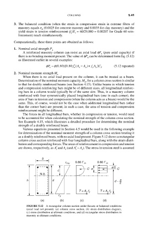
as a doubly reinforced beam, with no axial load present. Figure 5.12 shows a rectangular
column cross section reinforced with four longitudinal bars, along with the strain distri-
bution and corresponding forces. The areas of reinforcement in compression and tension
are shown, respectively, as ′ A and A (and ′ A = A ). The stress in tension steel is assumed
s s s s
b
0.80 f ʹ
e mu m 0.80 f ʹ m
a/2
C a C
c
N.A.
h d d – a
2
T = A s f y T = A s f s
e y
(a) (b) (c) (d)
FIGURE 5.12 A rectangular column section under flexure at balanced conditions
(axial load not present). (a) column corss section, (b) strain distribution diagram,
(c) stress distribution at ultimate conditions, and (d) rectangular stress distribution in
masonry at ultimate conditions.