
Page 316 - Design of Reinforced Masonry Structures
P. 316
5.36 CHAPTER FIVE
P u = 400 k
M n
C m = 37.8c K
c – 3
C s = 87 k
3
T = 72 k C m C s
FIGURE E5.9C
For vertical equilibrium, ΣFy = 0:
C + C – P – T = 0
m
u
s
( )
c −
3
−
=
37 8c + 87 − 400 72 0
.
c
2
37.8c – 385c – 261 = 0
The solution of the above quadratic equation is: c = 10.82 in. (the negative root is
ignored as it does not have any significance in this practical problem).
a = 0.8c = 0.8(10.82) = 8.66 in.
The values of C and C can now be calculated from the calculated value of c. Thus,
s
m
the forces acting on the column are
C = 37.8c = 37.8(10.82) = 409 kips
m
s ( ) ( 10 82 − 3 )
.
c − 3
.
C = 87 = 87 = 62 88kips
c 10 82
.
Check equilibrium: ΣF = 0:
y
C + C – P – T = 409 + 62.88 – 400 – 72
m
s
u
= – 0.12 kips ≈ 0 (rounding off
error)
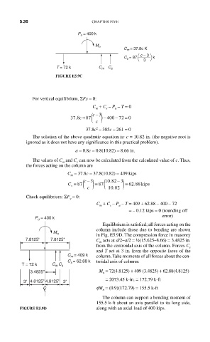
P u = 400 k
Equilibrium is satisfied; all forces acting on the
column include those due to bending are shown
M n
in Fig. E5.9D. The compression force in masonry
7.8125'' 7.8125'' C acts at d/2−a/2 = ½(15.625–8.66) = 3.4825 in.
m
from the centroidal axis of the column. Forces C s
and T act at 3 in. from the opposite faces of the
C m = 409 k column. Take moments of all forces about the cen-
C = 62.88 k troidal axis of column:
s
T = 72 k C m C s
3.4825'' M = 72(4.8125) + 409 (3.4825) + 62.88(4.8125)
n
= 2073.45 k- in. = 172.79 k-ft
3'' 4.8125'' 4.8125'' 3''
C L fM = (0.9)(172.79) = 155.5 k-ft
n
The column can support a bending moment of
155.5 k-ft about an axis parallel to its long side,
FIGURE E5.9D along with an axial load of 400 kips.