
Page 315 - Design of Reinforced Masonry Structures
P. 315
COLUMNS 5.35
e m = 0.0025 0.80 f¢
23.625'' m
3'' 3'' e′ s 3'' a
C s 2
a C m
15.625''
4#7 (d – a /2)
3'' f s = f y T = A s F y
3'' 3''
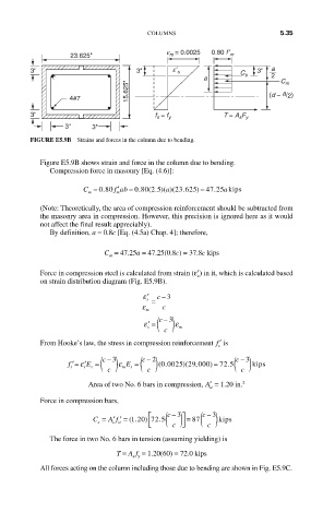
FIGURE E5.9B Strains and forces in the column due to bending.
Figure E5.9B shows strain and force in the column due to bending.
Compression force in masonry [Eq. (4.6)]:
′
C = 0 80. f ab = 0 80 2 5. ( . )( a 23 625)( . ) = 47 25 akips
.
m
m
(Note: Theoretically, the area of compression reinforcement should be subtracted from
the masonry area in compression. However, this precision is ignored here as it would
not affect the final result appreciably).
By definition, a = 0.8c [Eq. (4.5a) Chap. 4]; therefore,
C = 47.25a = 47.25(0.8c) = 37.8c kips
m
Force in compression steel is calculated from strain (ε′) in it, which is calculated based
s
on strain distribution diagram (Fig. E5.9B).
′ ε s c − 3
ε = c
m
c
− 3
ε ′ = ( ) ε
s
c m
From Hooke’s law, the stress in compression reinforcement ′ f is
s
− 3
− 2
c
c
− 3
c
f s ′= ′Eε s s = ( ) ε m E s = ( ) (. ) ( , = ( ) kips
0 0025 29 000) = 72 5.
c c c
Area of two No. 6 bars in compression, ′ A = 1.20 in. 2
st
Force in compression bars,
c − 3
⎡ ( ) ⎤ ( )
c − 3
)
.
A f
C = ′′ = (.120 725 = 87 kiips
s s st ⎣ ⎢ c ⎦ ⎥ c
The force in two No. 6 bars in tension (assuming yielding) is
T = A f = 1.20(60) = 72.0 kips
s y
All forces acting on the column including those due to bending are shown in Fig. E5.9C.