
Page 317 - Design of Reinforced Masonry Structures
P. 317
COLUMNS 5.37
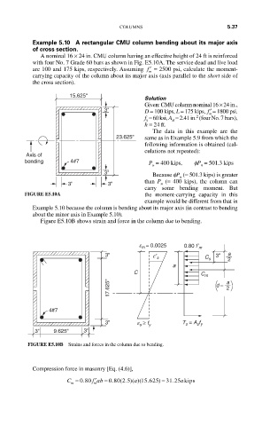
Example 5.10 A rectangular CMU column bending about its major axis
of cross section.
A nominal 16 × 24 in. CMU column having an effective height of 24 ft is reinforced
with four No. 7 Grade 60 bars as shown in Fig. E5.10A. The service dead and live load
are 100 and 175 kips, respectively. Assuming ′ f = 2500 psi, calculate the moment-
m
carrying capacity of the column about its major axis (axis parallel to the short side of
the cross section).
15.625''
Solution
Given: CMU column nominal 16 × 24 in.,
3'' D = 100 kips, L = 175 kips, ′ f = 1800 psi.
m
2
f = 60 ksi, A = 2.41 in. (four No. 7 bars),
y st
h = 24 ft.
The data in this example are the
23.625'' same as in Example 5.9 from which the
following information is obtained (cal-
culations not repeated):
Axis of
bending 4#7 P = 400 kips, fP = 501.3 kips
u n
3'' Because fP (= 501.3 kips) is greater
n
than P (= 400 kips), the column can
3'' 3'' u
carry some bending moment. But
FIGURE E5.10A the moment-carrying capacity in this
example would be different from that in
Example 5.10 because the column is bending about its major axis (in contrast to bending
about the minor axis in Example 5.10).
Figure E5.10B shows strain and force in the column due to bending.
e m = 0.0025 0.80 f’ m
3'' 3'' a
e′ s
C s 2
a
C
C m
17.625'' d – a 2
4#7
3'' e s ≥ f y T s = A s f y
3'' 9.625'' 3''
FIGURE E5.10B Strains and forces in the column due to bending.
Compression force in masonry [Eq. (4.6)],
′
C = 0 80. f ab = 0 80 2 5. ( . )( a 15 625)( . ) = 31 25 akips
.
m
m