
Page 312 - Design of Reinforced Masonry Structures
P. 312
5.32 CHAPTER FIVE
Force in compression steel is calculated from strain ( ′ ε ) in it, which is calculated from
s
the strain distribution diagram (Fig. E5.8B).
′ ε c − 3
s =
ε m c
− 3
c
ε
′ = ( ) ε
s m
c
From Hooke’s law, the stress in compression reinforcement ′ f is
s
( ) ( ) ( )
− 3
c
c
− 3
c
− 3
′= ′Eε = ε E = (. ) ( , = kips
0 0025 29 000) = 72 5.
f
s s s m s
c c c
Area of two No. 6 bars in compression, ′ A = 0.88 in. 2
s
Force in compression bars,
⎡ c − 3 ⎤ ( )
c − 3
)
A f
C = ′′= (.088 725 = 63 .8 k kips
.
s s s ⎣ ⎢ ( ) ⎥ ⎦ c
c
The force in two No. 6 bars in tension (assuming yielding) is
T = A f = 0.88(60) = 52.8 kips
s y
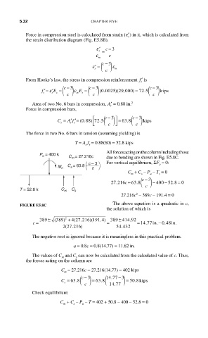
All forces acting on the column including those
P u = 400 k
C m = 27.216c due to bending are shown in Fig. E5.8C.
c – 3 For vertical equilibrium, ΣF = 0:
C s = 63.8 y
M n c
C + C – P – T = 0
u
s
m
s
c −
3
−
27 216c + 63 8 ( ) − 400 52 8 0
=
.
.
.
T = 52.8 k C m C s c
2
27.216c – 389c – 191.4 = 0
The above equation is a quadratic in c,
FIGURE E5.8C
the solution of which is
)(
(
.
c = 389 ± ( 389) 2 + 4 27 216 191 4 . ) = 389 ± 4414 92. = 14 77in. − 0 48in.
.
.
.
227216) 54 432
.
(
The negative root is ignored because it is meaningless in this practical problem.
a = 0.8c = 0.8(14.77) = 11.82 in.
The values of C and C can now be calculated from the calculated value of c. Thus,
m
s
the forces acting on the column are
C = 27.216c = 27.216(14.77) = 402 kips
m
.
c − 3
C = 63 8. ( ) = 63 8 ( 14 77 − 3 ) = 50 8.kips
.
s
.
c 14 77
Check equilibrium:
C + C – P – T = 402 + 50.8 – 400 – 52.8 = 0
s
u
m