
Page 307 - Design of Reinforced Masonry Structures
P. 307
COLUMNS 5.27
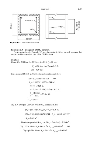
#3
#3@14 in.
23.625'' #9 #3 Ties @ 14 o.c. (typ)
4#7
#3
23.625''
FIGURE E5.6 Details of reinforcement.
Example 5.7 Design of a CMU column.
For the data given in Example 5.6, specify a suitable higher strength masonry that
can be used for a nominal 16 × 16 in. CMU column.
Solution
Given: D = 250 kips, L = 200 kips, h = 20 ft, f = 60 ksi.
y
P = 620 kips (see Example 5.5)
u
fP = 620 kips
n
For a nominal 16 × 16 in. CMU column (from Example 5.5):
h/t = 20(12)/16 = 15 < 30 OK
A = (15.625)(15.625) = 244 in. 2
n
b = t = 15.625 in.
r = 0.289t = 0.289(15.625) = 4.52 in.
12
h (20 )( )
= = 53 .1 < 99
r . 452
C = 0.937
P
Try ′ f = 2000 psi. Calculate required A from Eq. (5.20).
m
st
]
)
φP = φ(.080 )[.080 f ′( A − A + f A C
n
m
st
n
s
P
y
620 = 0.9(0.80)[0.80 (2.0)(244 – A ) + (60)(A )](0.937)
st
st
A = 9.05 in. 2
st
Maximum permissible A = 0.04A = 0.04(244) = 9.76 in. 2
s t
n
2
2
Try 12 No. 8 bars, A = 8.64 in. < A st, reqd = 9.05 in. NG
st
2
Try eight No. 9 bars, A = 9.0 in. ≈ A st, reqd = 9.05 in. 2
st