
Page 309 - Design of Reinforced Masonry Structures
P. 309
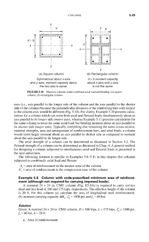
COLUMNS                          5.29

                            y
                               b                      y  b


                d = b
                                             d
                 x                     x
                                           x                     x


                            y
                                                      y
                      (a) Square column:       (b) Rectangular column:
                     Symmetrical about x-axis   d > b moment capacity
                 and y-axis, moment capacity about  about x-axis and y-axis
                      the two axis is same.       is not the same.
                FIGURE 5.10  Masonry columns under combined axial load and bending: (a) square
                column, (b) rectangular column.

         axes (i.e., axis parallel to the longer side of the column and the axis parallel to the shorter
         side of the column) because the perpendicular distances of the reinforcing bars with respect
         to the column axes would be different (Fig. 5.10). For clarity, Example 5.10 presents calcu-
         lations for a column which can resist both axial and flexural loads simultaneously about an
         axis parallel to its longer side (minor axis), whereas Example 5.11 presents calculations for
         the same column to resist the same axial load, but bending moment about an axis parallel to
         its shorter side (major axis). Typically, everything else remaining the same (cross section,
         material strengths, area and arrangement of reinforcement bars, and axial load), a column
         would resist larger moment about an axis parallel to shorter side as compared to moment
         about the axis parallel to its longer side.
           The axial strength of a column can be determined as discussed in Section 5.2. The
         flexural strength of a column can be determined as discussed in Chap. 4. A general method
         for designing a column subjected to simultaneous axial and flexural loads is presented in
         the next subsection.
           The following notation is specific to Examples 5.8–5.11 in this chapter (for columns
         subjected to combined): axial load and flexure:
            A  = area of reinforcement in the tension zone of the column
             s
           A′  = area of reinforcement in the compression zone of the column
            s

           Example 5.8  Column with code-prescribed minimum area of reinforce-
           ment (although not required for carrying imposed loads).
             A nominal 24 × 24 in. CMU column (Fig. E5.8A) is required to carry service
           dead and live load of 100 and 175 kips, respectively. The effective height of the column
           is 20 ft. For this column (a) calculate the area of longitudinal steel reinforcement,
           (b) moment-carrying capacity fM .  ′ f  = 1800 psi and f  = 60 ksi.
                                   n  m           y
           Solution
           Given: A nominal 24 × 24 in. CMU column, D = 100 kips, L = 175 kips,  ′ f  = 1800 psi.
                                                                m
           f  = 60 ksi, h = 20 ft.
           y
             a.  Area of reinforcement: