
Page 378 - Design of Reinforced Masonry Structures
P. 378
WALLS UNDER GRAVITY AND TRANSVERSE LOADS 6.29
H
F G
E
H
F
G
E
Equal C
MWFRS direction
being evacuated Reference A h
corner
Equal
h MWFRS direction
C
being evacuated
A Reference
corner
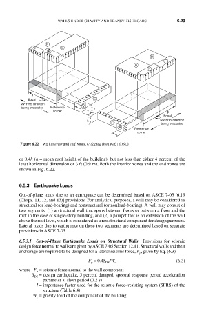
Figure 6.22 Wall interior and end zones. (Adapted from Ref. [6.19].)
or 0.4h (h = mean roof height of the building), but not less than either 4 percent of the
least horizontal dimension or 3 ft (0.9 m). Both the interior zones and the end zones are
shown in Fig. 6.22.
6.5.3 Earthquake Loads
Out-of-plane loads due to an earthquake can be determined based on ASCE 7-05 [6.19
(Chaps. 11, 12, and 13)] provisions. For analytical purposes, a wall may be considered as
structural (or load-bearing) and nonstructural (or nonload-bearing). A wall may consist of
two segments: (1) a structural wall that spans between floors or between a floor and the
roof in the case of single-story building, and (2) a parapet that is an extension of the wall
above the roof level, which is considered as a nonstructural component for design purposes.
Lateral loads due to earthquake on these two segments are determined based on separate
provisions in ASCE 7-05.
6.5.3.1 Out-of-Plane Earthquake Loads on Structural Walls Provisions for seismic
design force normal to walls are given by ASCE 7-05 Section 12.11. Structural walls and their
anchorage are required to be designed for a lateral seismic force, F , given by Eq. (6.3):
p
F = 0.4S IW (6.3)
p DS c
where F = seismic force normal to the wall component
p
S = design earthquake, 5 percent damped, spectral response period acceleration
DS
parameter at short period (0.2 s)
I = importance factor used for the seismic force–resisting system (SFRS) of the
structure (Table 6.4)
W = gravity load of the component of the building
c