
Page 379 - Design of Reinforced Masonry Structures
P. 379
6.30 CHAPTER SIX
TABLE 6.4 Importance Factor for Seismic Loads
(Adapted from Ref. 6.19)
Occupancy category* I II III IV
Importance factor 1.0 1.0 1.25 1.5
*Refer to ASCE 7-5 [6.19] Table 1-1 for details of occu-
pancy categorization.
The value of the lateral force F given by Eq. (6.3) is limited to the following values:
p
1. Force F may not be less than that given by Eq. (6.4)
p
F p,min = 0.1W (6.4)
c
2. The anchorage of concrete or masonry walls to supporting construction shall provide
a direct connection capable of resisting a force equal to or greater of the following to
prevent the separation of these walls from the roof or floor diaphragms:
(a) F given by Eq. (6.3)
p
(b) A force equal to 400SDS I per linear foot of the wall
(c) 280 lb per linear foot of the wall
The importance factor I is assigned three values: 1.0, 1.25, and 1.5 based on the occu-
pancy category of the structure (see ASCE 7-05 Table 1-1), as listed in Table 6.4.
In Eq. (6.3), S is determined from the Eq. (6.5):
DS
2
S = / 3S (6.5)
MS
DS
where S = the maximum considered earthquake, 5 percent damped, spectral response
MS
parameter at short periods (0.2 s) adjusted for site class effects. This adjust-
ment is made from Eq. (6.6):
S = F S (6.6)
a s
MS
where F = short period (0.2 s), coefficient adjusted for site class as listed in ASCE 7-05
a
Table 11.4-1.
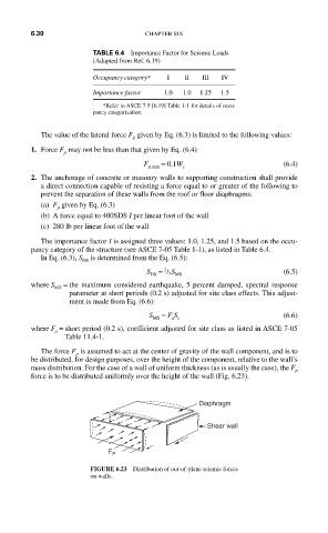
The force F is assumed to act at the center of gravity of the wall component, and is to
p
be distributed, for design purposes, over the height of the component, relative to the wall’s
mass distribution. For the case of a wall of uniform thickness (as is usually the case), the F
p
force is to be distributed uniformly over the height of the wall (Fig. 6.23).
Diaphragm
Shear wall
F P
FIGURE 6.23 Distribution of out-of-plane seismic forces
on walls.