
Page 383 - Design of Reinforced Masonry Structures
P. 383
6.34 CHAPTER SIX
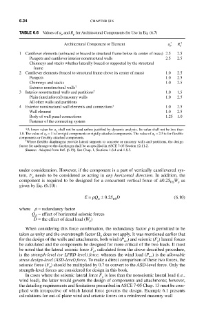
TABLE 6.6 Values of a and R for Architectural Components for Use in Eq. (6.7)
p
p
Architectural Component or Element a p * R p †
1 Cantilever elements (unbraced or braced to structural frame below its center of mass) 2.5 2.5
Parapets and cantilever interior nonstructural walls 2.5 2.5
Chimneys and stacks whether laterally braced or supported by the structural
frame
2 Cantilever elements (braced to structural frame above its center of mass) 1.0 2.5
Parapets 1.0 2.5
Chimneys and stacks 1.0 2.5
Exterior nonstructural walls †
3 Interior nonstructural walls and partitions † 1.0 1.5
Plain (unreinforced) masonry walls 1.0 2.5
All other walls and partitions
4 Exterior nonstructural wall elements and connections † 1.0 2.5
Wall element 1.0 2.5
Body of wall panel connections 1.25 1.0
Fastener of the connecting system
*A lower value for a p shall not be used unless justified by dynamic analysis. Its value shall not be less than
1.0. The value of a p = 1 is for rigid components or rigidly attached components. The value of a p = 2.5 is for flexible
components or flexibly attached components.
† Where flexible diaphragms provide lateral supports to concrete or masonry walls and partitions, the design
forces for anchorage to the diaphragm shall be as specified in ASCE 7-05 Section 12.11.2.
Source: Adapted from Ref. [6.19]. See Chap. 1, Sections 1.8.4 and 1.8.5.
under consideration. However, if the component is a part of vertically cantilevered sys-
tem, F needs to be considered as acting in any horizontal direction. In addition, the
p
component is required to be designed for a concurrent vertical force of ±0.2S W as
p
DS
given by Eq. (6.10):
E = rQ ± 0.2S D (6.10)
DS
E
where r = redundancy factor
Q = effect of horizontal seismic forces
E
D = the effect of dead load (W )
p
When considering this force combination, the redundancy factor r is permitted to be
taken as unity and the overstrength factor Ω does not apply. It was mentioned earlier that
ο
for the design of the walls and attachments, both wind (P ) and seismic (F ) lateral forces
net
p
be calculated and the components be designed for more critical of the two loads. It must
be noted that the lateral seismic force F , calculated from the above described procedure,
p
is the strength-level (or LFRD-level) force, whereas the wind load (P ) is the allowable
nrt
stress design-level (ASD-level) force. To make a direct comparison of these two forces, the
seismic force (F ) should be multiplied by 0.7 to convert to the ASD-level force. Only the
p
strength-level forces are considered for design in this book.
In cases where the seismic lateral force F is less than the nonseismic lateral load (i.e.,
p
wind load), the latter would govern the design of components and attachments; however,
the detailing requirements and limitations prescribed in ASCE 7-05 Chap. 13 must be com-
plied with irrespective of which lateral force governs the design. Example 6.1 presents
calculations for out-of-plane wind and seismic forces on a reinforced masonry wall