
Page 384 - Design of Reinforced Masonry Structures
P. 384
WALLS UNDER GRAVITY AND TRANSVERSE LOADS 6.35
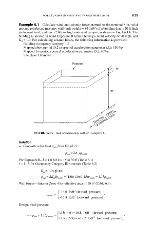
Example 6.1 Calculate wind and seismic forces normal to the nominal 8-in. solid
2
grouted reinforced masonry wall (unit weight = 84 lb/ft ) of a building that is 20 ft high
to the roof level, and has a 2 ft 8 in. high unbraced parapet, as shown in Fig. E6.1A. The
building is located in wind Exposure B terrain having a wind velocity of 90 mph, and
K = 1.0. For calculating seismic forces, the following information is provided:
zt
Building occupancy category: III
Mapped short period (0.2 s) spectral acceleration parameter (S ): 150%g
S
Mapped 1-s period spectral acceleration parameter (S ): 90%g
1
Site class: Unknown
Parapet
2' – 8"
20'
Direction of wind
or seismic loads
FIGURE E6.1A Reinforced masonry wall for Example 6.1.
Solution
a. Calculate wind load p from Eq. (6.1):
net
p = λK Ip
net zt net30
For Exposure B, l = 1.0 for h = 15 to 30 ft (Table 6.1)
I = 1.15 for Occupancy Category III structure (Table 6.2)
K = 1.0 (given)
zt
p = lK Ip net30 = (1.0)(1.0)(1.15)p net30 = 1.15p net30
net
zt
Wall forces—Interior Zone 4 for effective area of 10 ft (Table 6.3):
2
⎧ ⎪ 14 6 lb/ft (inward pressure) ⎫ ⎪
2
.
p net30 = ⎨ ⎬
⎩ ⎪ − 15 8 lb/ft (outwarrd pressure) ⎭ ⎪
2
.
Design wind pressure:
⎧ ⎪ 115 146) = 168 lb/ft 2 (inward pressure) ⎫ ⎪
.
(
.
.
w = p = 1.15p net30 = ⎨ ⎬
net
⎩ ⎪ 115(−115 8.) =− 18 2 lb/ft 2 (outward pressure)⎪
⎭ ⎭
.
.