
Page 388 - Design of Reinforced Masonry Structures
P. 388
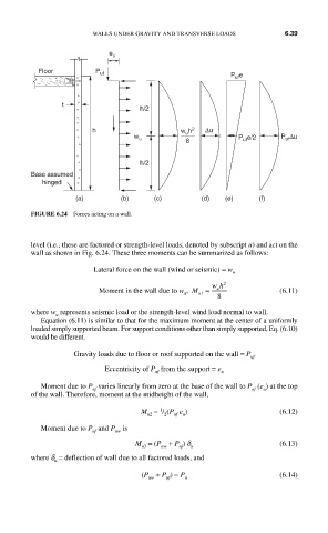
WALLS UNDER GRAVITY AND TRANSVERSE LOADS      6.39


                           e u
          Floor         P uf
                                                         P uf e


                t
                                   h/2

                       h                     w u h 2  ∆u
                                  w u                      P uf e/2  P ∆u
                                                                      uf
                                              8
                                   h/2
         Base assumed
           hinged
                   (a)        (b)     (c)         (d)   (e)     (f)

         FIGURE 6.24  Forces acting on a wall.


         level (i.e., these are factored or strength-level loads, denoted by subscript u) and act on the
         wall as shown in Fig. 6.24. These three moments can be summarized as follows:

                        Lateral force on the wall (wind or seismic) = w
                                                         u
                                                      u
                         Moment in the wall due to w ,  M =  wh 2    (6.11)
                                              u
                                                 u1
                                                      8
         where w  represents seismic load or the strength-level wind load normal to wall.
               u
           Equation (6.11) is similar to that for the maximum moment at the center of a uniformly
         loaded simply supported beam. For support conditions other than simply supported, Eq. (6.10)
         would be different.
                   Gravity loads due to floor or roof supported on the wall = P uf
                          Eccentricity of P  from the support = e u
                                       uf
           Moment due to P uf     varies linearly from zero at the base of the wall to P  (e ) at the top
                                                                 u
                                                              uf
         of the wall. Therefore, moment at the midheight of the wall,
                                        1
                                   M  =  / (P  e )                   (6.12)
                                     u2  2  uf  u
           Moment due to P  and P  is
                       uf    uw
                                  M  = (P  + P ) d                   (6.13)
                                               u
                                        uw
                                   u3
                                            uf
         where d  = deflection of wall due to all factored loads, and
              u
                                   (P  + P ) = P                     (6.14)
                                     uw
                                         uf
                                              u