Page 389 - Design of Reinforced Masonry Structures
P. 389
6.40                       CHAPTER SIX

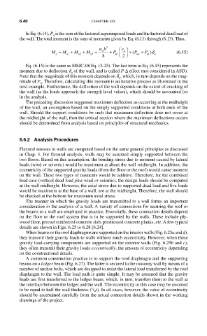
           In Eq. (6.14), P  is the sum of the factored superimposed loads and the factored dead load of
                     u
         the wall. The total moment is the sum of moments given by Eq. (6.11) through (6.13). Thus,
                                                           δ
                                                 u
                                        u
                     M =  M +  M +  M =  wh 2  +  P ⎜ ⎛  e ⎞ ⎟ + ( P +  P )δ  (6.15)
                      u    u1  u2   u3       uf  ⎠   uw  uf  u
                                        8      ⎝ 2
           Eq. (6.15) is the same as MSJC-08 Eq. (3-25). The last term in Eq. (6.15) represents the
         moment due to deflection d  of the wall, and is called P-∆ effect (not considered in ASD).
                            u
         Note that the magnitude of this moment depends on d , which, in turn depends on the mag-
                                               u
         nitude of P . Therefore, calculating this moment is an iterative process as illustrated in the
                 u
         next example. Furthermore, the deflection of the wall depends on the extent of cracking of
         the wall (as the loads approach the strength level values), which should be accounted for
         in the analysis.
           The preceding discussion suggested maximum deflection as occurring at the midheight
         of the wall, an assumption based on the simply supported conditions at both ends of the
         wall. Should the support conditions be such that maximum deflection dose not occur at
         the midheight of the wall, then the critical section where the maximum deflections occurs
         should be determined from analysis based on principles of structural mechanics.
         6.6.2 Analysis Procedures
         Flexural stresses in walls are computed based on the same general principles as discussed
         in Chap. 4. For flexural analysis, walls may be assumed simply supported between the
         two floors. Based on this assumption, the bending stress due to moment caused by lateral
         loads (wind or seismic) would be maximum at about the wall midheight. In addition, the
         eccentricity of the supported gravity loads (from the floor or the roof) would cause moment
         on the wall. These two types of moments would be additive. Therefore, for the combined
         load case (vertical dead load plus wind or seismic), the design loads should be computed
         at the wall midheight. However, the axial stress due to supported dead load and live loads
         would be maximum at the base of a wall, not at the midheight. Therefore, the wall should
         be checked at the bottom for maximum axial stress.
           The manner in which the gravity loads are transmitted to a wall forms an important
         consideration in the analysis of a wall. A variety of connections for securing the roof or
         the beams to a wall are employed in practice. Essentially, these connection details depend
         on the floor or the roof system that is to be supported by the walls. These include ply-
         wood floor, precast reinforced concrete slab, prestressed concrete planks, etc. A few typical
         details are shown in Figs. 6.25 to 6.28 [6.24].
           When beams or the roof diaphragms are supported on the interior walls (Fig. 6.25a and d),
         they transmit their gravity loads to walls without much eccentricity. However, when these

         gravity load-carrying components are supported on the exterior walls (Fig. 6.25b and c),
         they often transmit their gravity loads eccentrically, the amount of eccentricity depending
         on the constructional details.
           A common construction practice is to support the roof diaphragm and the supporting
         beams on a ledger beam (Fig. 6.27). The latter is secured to the masonry wall by means of a
         number of anchor bolts, which are designed to resist the lateral load transferred by the roof
         diaphragm to the wall. The load path is quite simple. It may be assumed that the gravity
         loads are first transferred to the ledger beam, which, in turn, transfers them to the wall at
         the interface between the ledger and the wall. The eccentricity in this case may be assumed
                                    1
         to be equal to half the wall thickness ( / 2t). In all cases, however, the value of eccentricity
         should be ascertained carefully from the actual connection details shown in the working
         drawings of the project.

