
Page 394 - Design of Reinforced Masonry Structures
P. 394
WALLS UNDER GRAVITY AND TRANSVERSE LOADS 6.45
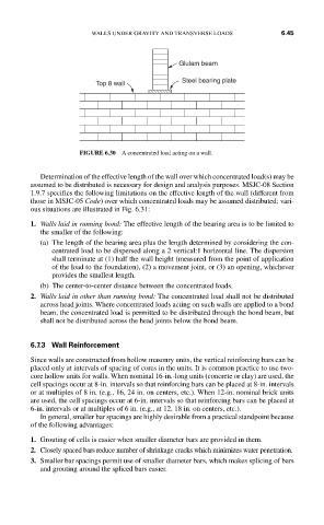
Glulam beam
Top 8 wall Steel bearing plate
FIGURE 6.30 A concentrated load acting on a wall.
Determination of the effective length of the wall over which concentrated load(s) may be
assumed to be distributed is necessary for design and analysis purposes. MSJC-08 Section
1.9.7 specifies the following limitations on the effective length of the wall (different from
those in MSJC-05 Code) over which concentrated loads may be assumed distributed; vari-
ous situations are illustrated in Fig. 6.31:
1. Walls laid in running bond: The effective length of the bearing area is to be limited to
the smaller of the following:
(a) The length of the bearing area plus the length determined by considering the con-
centrated load to be dispersed along a 2 vertical:1 horizontal line. The dispersion
shall terminate at (1) half the wall height (measured from the point of application
of the load to the foundation), (2) a movement joint, or (3) an opening, whichever
provides the smallest length.
(b) The center-to-center distance between the concentrated loads.
2. Walls laid in other than running bond: The concentrated load shall not be distributed
across head joints. Where concentrated loads acting on such walls are applied to a bond
beam, the concentrated load is permitted to be distributed through the bond beam, but
shall not be distributed across the head joints below the bond beam.
6.7.3 Wall Reinforcement
Since walls are constructed from hollow masonry units, the vertical reinforcing bars can be
placed only at intervals of spacing of cores in the units. It is common practice to use two-
core hollow units for walls. When nominal 16-in.-long units (concrete or clay) are used, the
cell spacings occur at 8-in. intervals so that reinforcing bars can be placed at 8-in. intervals
or at multiples of 8 in. (e.g., 16, 24 in. on centers, etc.). When 12-in. nominal brick units
are used, the cell spacings occur at 6-in. intervals so that reinforcing bars can be placed at
6-in. intervals or at multiples of 6 in. (e.g., at 12, 18 in. on centers, etc.).
In general, smaller bar spacings are highly desirable from a practical standpoint because
of the following advantages:
1. Grouting of cells is easier when smaller diameter bars are provided in them.
2. Closely spaced bars reduce number of shrinkage cracks which minimizes water penetration.
3. Smaller bar spacings permit use of smaller diameter bars, which makes splicing of bars
and grouting around the spliced bars easier.