
Page 395 - Design of Reinforced Masonry Structures
P. 395
6.46 CHAPTER SIX
P P
Slope 2:1 Bearing plate Bearing plate
Slope 2:1
Bond beam Bond beam
Head joint Head
joint
(a) Wall laid in running bond load dispersion (b) Wall laid in stack bond load dispersion
through head joints is permitted past the head joints is not permitted
P P P
Slope 2:1
Slope 2:1
h
2
h
Effective Effective
Effective length length length
(c) Single concentrated (d) Two adjgacent concentrated loads
load
P P
Slope 2:1 2:1 slope
End of
wall
Effective length Effective length
(e) Load dispearsion near (f) Load dispersion near a wall opening
the wall end
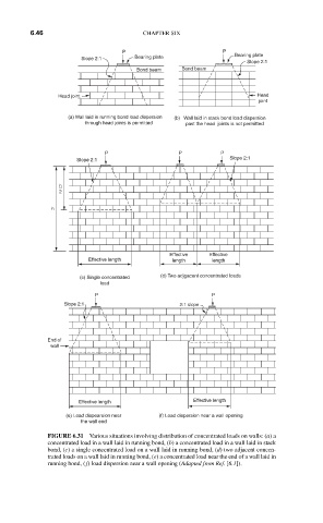
FIGURE 6.31 Various situations involving distribution of concentrated loads on walls: (a) a
concentrated load in a wall laid in running bond, (b) a concentrated load in a wall laid in stack
bond, (c) a single concentrated load on a wall laid in running bond, (d) two adjacent concen-
trated loads on a wall laid in running bond, (e) a concentrated load near the end of a wall laid in
running bond, ( f) load dispersion near a wall opening (Adapted from Ref. [6.1]).