
Page 397 - Design of Reinforced Masonry Structures
P. 397
6.48 CHAPTER SIX
TABLE 6.7 Maximum Bar Size for Various Size Units
12-in. Long Units 16-in. Long Units
Unit Thickness Cell Size Maximum Cell Size Maximum
(Nominal) (width × length) Bar Size (width × length) Bar Size
3
1
3
4 in. 1 / 4 × 3 / 2 5 1 / 4 × 3 5
1
1
5 in. 2 / 2 × 3 / 2 6 2 × 5 7
1
1
6 in. 3 / 2 × 3 / 2 7 3 × 5 8
1
8 in. 5 × 3 / 2 9 5 × 5 9
1
3
10 in. 6 / 4 × 3 / 2 10 6½ × 5 9
1
1
12 in. 8 / 2 × 3 / 2 11 85 9
In buildings, the windward face of the wall is subjected to compression and the back of the
wall to tension. The same applies in the case of seismic lateral loads also—the face exposed
to seismic loads is in flexural compression, and the opposite face in tension. Since the direc-
tion of wind and seismic forces can reverse, either face of the wall can be in tension or in
compression. Therefore, it is common practice to place the vertical reinforcing bars at the
center of the cells. However, based on structural requirements, bars can be placed on both
faces of the cells (discussed in Section 6.7.5).
In retaining walls and basement walls, which are subjected to earth pressure from one
side only, the stress conditions are somewhat different. In case of retaining wall, which
acts as a cantilever, the face of the wall in contact with the soil is in tension. The opposite
is true in case of basement wall. A basement wall may be assumed simply supported at the
floor levels. Consequently, the face of the wall exposed to soil would be in compression
and the opposite face in tension. In both cases, reinforcing bars will have to be placed near
the tension face of the wall.
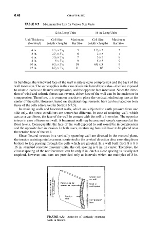
Since flexural stresses in a vertically spanning wall are directed in the vertical plane,
the tension resisting reinforcement is oriented in the vertical direction also, extending from
bottom to top, passing through the cells which are grouted. In a wall built from 8 × 8 ×
16 in. standard concrete masonry units, the cell spacing is 8 in. on center. Therefore, the
closest spacing of the reinforcement can be only 8 in. Such a close spacing is usually not
required, however, and bars are provided only at intervals which are multiples of 8 in.
FIGURE 6.33 Behavior of vertically spanning
walls in flexure.