
Page 400 - Design of Reinforced Masonry Structures
P. 400
WALLS UNDER GRAVITY AND TRANSVERSE LOADS 6.51
Brick, solid, cored, and hollow, are available in various sizes (modular and nonmodular)
as discussed in Chap. 2. Pertinent details for brick sizes and related information can be
found in the BIA Technical Notes [6.29 and 6.30]. The actual thickness of the wall will
depend on the type of bricks used and the type of wall constructed (e.g., two-wythe wall
with collar joint or a single-wythe wall, hollow or reinforced). Modular bricks are available
in widths of 4, 6, and 8 in. Nonmodular bricks have their actual dimensions smaller than
5
3
the nominal dimensions to allow for the mortar joint, generally / 8 to / 8 in; this permits
1
even-dimensional modular coursing. Thus, a 4-in. nominal brick may be actually 3 / 2 to
5
3 / 8 in. wide, and the effective depth, d, for the centrally reinforced wall would be half the
actual width of the brick.
It should be noted that dimensional variations may exist in the thicknesses of the web
and the end walls of hollow masonry units of various sizes, as well as in the masonry units
produced by different manufacturers. Therefore, it would be prudent to check with the
material supplier regarding the availability and the actual size of the masonry units to be
used for a project. Since these dimensions may not be known a priori or at the preliminary
design stage, information given in Table 6.4 may be used as a guide.
6.7.6 Effective Width: T-Beam Analysis
If a wall under flexure due to out-of-plane loads were solid grouted, it could be analyzed
as a (solid) rectangular section, using a 1-ft-wide vertical strip of the wall. But this analysis
can not be used when such a wall is partially grouted. This is because in a partially grouted
wall only those cells are grouted which contain reinforcing bars, leaving other cells as hol-
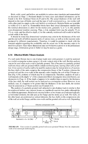
low. Cross section of such a wall to be used for analysis may be viewed akin to a T-section:
the face shells of the units comprise the compression flange of the T-section, whereas the
grouted cell and the cross-walls of the masonry units comprise the web of this T-beam sec-
tion (Fig. 6.36), portions of which may be in compression. Therefore, analysis of such a
wall depends on the depth “a” of the compression block (rectangular stress distribution, see
discussion in Chap. 4). If the depth a happens to be smaller than or equal to the thickness
of the face shell, the wall section can be analyzed as a rectangular section. However, in an
unlikely case, if a happens to be greater than the thickness of the face shells, the section
must be analyzed as a T-beam section (see Example 6.5).
The analysis of a partially grouted wall subjected to out-of-plane loads is similar to that
for reinforced hollow core concrete beams or a multiweb concrete box girder although the
two differ in appearance. Reinforced concrete hollow or box beams are positioned typically
as horizontal elements; the slab acts as the flange and the stems act as web. The walls, on
the other hand, are positioned as vertical elements; the face shells on the compression side
of the wall act as the flange, and the cross-walls and the grouted cells act as web. Depending
Effective compression width
t
1" f
1
4
d
5" 1" t
7 1 1"
8
4
Nominal 8 × 8 × 16 CMU Mortar
b´ Grout
(Web)
FIGURE 6.36 Cross section of a partially grouted wall as an equivalent T-Beam. Note the compression
width of the section per reinforcing bar.