
Page 396 - Design of Reinforced Masonry Structures
P. 396
WALLS UNDER GRAVITY AND TRANSVERSE LOADS 6.47
A fundamental requirement of reinforced masonry construction is that all reinforcing
bars shall be embedded in grout (MSJC-05 Section 1.13.1). Reinforcement should be com-
pletely surrounded by and bonded to masonry material so that they work in unison to resist
loads. This is a basic assumption made for designing reinforced masonry. It follows that
there should be ample space in the cell of a masonry unit for grout to effectively surround
a reinforcing bar placed inside that cell.
Reinforcing bars must be placed in the cells prior to grouting, and they should be
secured against displacement prior to grouting by wire positioners or other suitable devices
at intervals not exceeding 200-bar diameters. However, construction practices vary some-
what. Horizontal reinforcing bars are positioned as the wall is erected. Vertical bars may
be installed prior to laying masonry or may be inserted from the top after the masonry is
placed to story height.
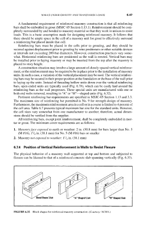
A construction situation may involve a large amount of closely spaced vertical reinforce-
ment, or the reinforcement may be required to be in place prior to the installation of masonry
units. In such a case, a variation of the vertical placement may be used. The vertical reinforc-
ing bars may be secured in their proper position at the foundation or the base of the wall prior
to laying up the units. Instead of threading hollow units down over the vertical reinforcing
bars, open-ended units are typically used (Fig. 6.7b), which can be easily laid around the
reinforcing bars as the wall progresses. These special units are manufactured with one or
both end webs removed, resulting in “A” or “H”—shaped units (Fig. 6.32).
Pertinent reinforcing bar requirements are specified in MSJC-05 Section 1.13 and 3.3.
The maximum size of reinforcing bar permitted is No. 9 for strength design of masonry.
Furthermore, the maximum reinforcement area in a cell or in a course is limited to 4 percent of
the cell area. Table 6.7 presents typical maximum bar size for the standard units. However,
the cell sizes vary somewhat from one manufacturer to another; therefore, actual dimen-
sions should be verified from the supplier.
All reinforcing bars, except joint reinforcement, shall be completely embedded in mor-
tar or grout. The minimum cover requirements are as follows:
1. Masonry face exposed to earth or weather: 2 in. (50.8 mm) for bars larger than No. 5
1
(M #16), 1 / 2 in. (38.1 mm) for No. 5 (M #16) bars or smaller
1
2. Masonry not exposed to weather: 1 / in. (38.1 mm)
2
6.7.4 Position of Vertical Reinforcement in Walls to Resist Flexure
The physical behavior of a masonry wall supported at top and bottom and subjected to
flexure can be likened to that of a reinforced concrete slab spanning vertically (Fig. 6.33).
FIGURE 6.32 Block shapes for reinforced masonry construction. (Courtesy: NCMA.)