
Page 398 - Design of Reinforced Masonry Structures
P. 398
WALLS UNDER GRAVITY AND TRANSVERSE LOADS 6.49
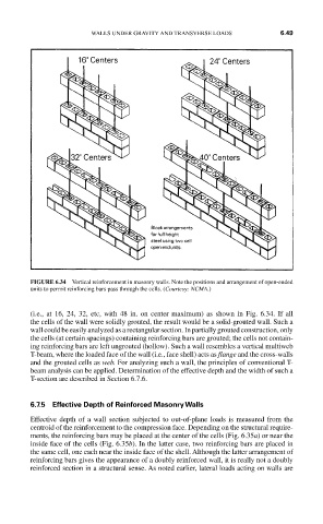
FIGURE 6.34 Vertical reinforcement in masonry walls. Note the positions and arrangement of open-ended
units to permit reinforcing bars pass through the cells. (Courtesy: NCMA.)
(i.e., at 16, 24, 32, etc, with 48 in. on center maximum) as shown in Fig. 6.34. If all
the cells of the wall were solidly grouted, the result would be a solid-grouted wall. Such a
wall could be easily analyzed as a rectangular section. In partially grouted construction, only
the cells (at certain spacings) containing reinforcing bars are grouted; the cells not contain-
ing reinforcing bars are left ungrouted (hollow). Such a wall resembles a vertical multiweb
T-beam, where the loaded face of the wall (i.e., face shell) acts as flange and the cross-walls
and the grouted cells as web. For analyzing such a wall, the principles of conventional T-
beam analysis can be applied. Determination of the effective depth and the width of such a
T-section are described in Section 6.7.6.
6.7.5 Effective Depth of Reinforced Masonry Walls
Effective depth of a wall section subjected to out-of-plane loads is measured from the
centroid of the reinforcement to the compression face. Depending on the structural require-
ments, the reinforcing bars may be placed at the center of the cells (Fig. 6.35a) or near the
inside face of the cells (Fig. 6.35b). In the latter case, two reinforcing bars are placed in
the same cell, one each near the inside face of the shell. Although the latter arrangement of
reinforcing bars gives the appearance of a doubly reinforced wall, it is really not a doubly
reinforced section in a structural sense. As noted earlier, lateral loads acting on walls are