
Page 402 - Design of Reinforced Masonry Structures
P. 402
WALLS UNDER GRAVITY AND TRANSVERSE LOADS 6.53
Therefore, in flexural computations, the value of b to be used for this 8-in. (nominal)
e
wall would be 32 in. (the least of the above three values). As a second example, consider a
6-in. wall (nominal) reinforced at 48 in. on centers. The effective width b of the wall will
e
be the least of the following:
1. Center-to-center distance between the reinforcement = 48 in.
2. Six times the (nominal) wall thickness = (6)(6) = 36 in.
3. 72 in.
Therefore, b = 36 in. (the least of the three values) will be used for all flexural calcu-
e
lations for this 6-in. (nominal) wall. The steel ratio, ρ (= A /bd), and the corresponding
s
moment strength (M ) will be computed with b = 36 in. However, the out-of-plane load
e
u
(causing moment and shear in the wall) that must be carried by this T-beam would be
computed for a tributary width of 48 in. (center-to-center distance between the reinforcing
bars). That is, in essence, 36-in. width of the wall carries out-of-plane load on 48-in. width
of the wall. This is the general principle used for designing T-beams.
It is noted that a wall constructed in stack bond is severely penalized. The reason
for this is that masonry walls are stronger if the horizontal courses of masonry units are
staggered so that the vertical joints are not continuous. A wall with continuous vertical
joints (i.e., stack bond) acts more like a series of adjacent, vertical piers, rather than
a cohesive unit. The interlocking bond has a further merit of dispersing loads evenly
(Figs. 6.19 and 6.31).
Analysis of a T-section depends on the location of the neutral axis which may lie in the
flange (i.e., within the face shell of the masonry unit) or in the web. Thus, two cases may
be considered:
1. If the depth of compressions block a is less than or equal to the thickness of the face
shell, the wall cross section can be analyzed as a rectangular section.
2. If the depth of compressions block a is greater than the thickness of the face shell so that
it extends in the web, the section would have to be analyzed as a T-section. This would
require that both the face shells and portions of webs be considered as contributing to
compression area. The analysis in this case can be simplified by considering the com-
pression stress resultant as the sum of two components: one contributed by the flange
and the other by a portion of the web (the grouted cell).
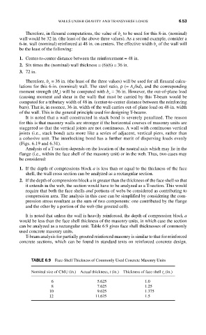
It is noted that unless the wall is heavily reinforced, the depth of compression block a
would be less than the face shell thickness of the masonry units, in which case the section
can be analyzed as a rectangular unit. Table 6.9 gives face shell thicknesses of commonly
used concrete masonry units.
T-beam analysis for partially grouted reinforced masonry is similar to that for reinforced
concrete sections, which can be found in standard texts on reinforced concrete design.
TABLE 6.9 Face-Shell Thickness of Commonly Used Concrete Masonry Units
Nominal size of CMU (in.) Actual thickness, t (in.) Thickness of face shell t s (in.)
6 5.625 1.0
8 7.625 1.25
10 9.625 1.375
12 11.625 1.5