Page 414 - Design of Reinforced Masonry Structures
P. 414

WALLS UNDER GRAVITY AND TRANSVERSE LOADS      6.65

                                                                       2
             Provide No. 4 horizontal bars spaced at 24 in. on center vertically; A  = 0.1 in.  >
                                                                s
                 2
           0.064 in. .
                                                         2
                                           2
                  Total A  = 0.15 + 0.064 = 0.214 in.  > A s,min  = 0.183 in.   OK
                       s
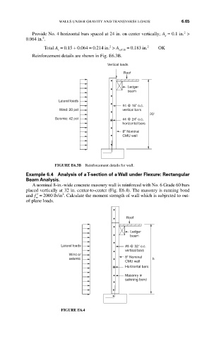
             Reinforcement details are shown in Fig. E6.3B.
                                          Vertical loads
                                                Roof
                                                  Ledger
                                                  beam
                       Lateral loads
                                                #4 @ 16" o.c.
                        Wind: 20 pst            vertical bars
                                                          20'
                      Seismic: 42 pst           #4 @ 24" o.c.
                                                horizontal bars
                                                8" Nominal
                                                CMU wall


                      FIGURE E6.3B Reinforcement details for wall.
           Example 6.4  Analysis of a T-section of a Wall under Flexure: Rectangular
           Beam Analysis.
             A nominal 8-in.-wide concrete masonry wall is reinforced with No. 6 Grade 60 bars
           placed vertically at 32 in. center-to-center (Fig. E6.4). The masonry is running bond
                         2
           and ′ =f  2000 lb/in . Calculate the moment strength of wall which is subjected to out-
               m
           of-plane loads.

                                                 Roof

                                                   Ledger
                                                   beam
                                                 #6 @ 32" o.c.
                        Lateral loads
                                                 vertical bars
                           Wind or
                           seismic               8" Nominal  h
                                                 CMU wall
                                                 Horizontal bars
                                                 Masonry in
                                                 selnning bond


                        FIGURE E6.4
   409   410   411   412   413   414   415   416   417   418   419