
Page 417 - Design of Reinforced Masonry Structures
P. 417
6.68 CHAPTER SIX
Because C < T, additional compressive force is required to maintain equilibrium, which
must be provided by additional masonry area in compression (in the web).
Additional compression force required (provided by the web)
C = 47.4 − 36 = 11.4 kips
w
2
f m ′ = 15. /in.
.
C 11 4
Additional area required = w = = 95 in. 2
.
.
(
.
080 f ′ 080 15)
.
m
b = 24 in.
e
In a length of b = 24 in., the total thickness of the cross-walls and the grouted cells = 6 in.
e
(grouted cells) + 3 × 1.25 in. (cross-walls) + 1.5 in. (web) = 11.25 in. (see Fig. 6.36).
95 .
Depth of web required = = 084 in.
.
.
11 25
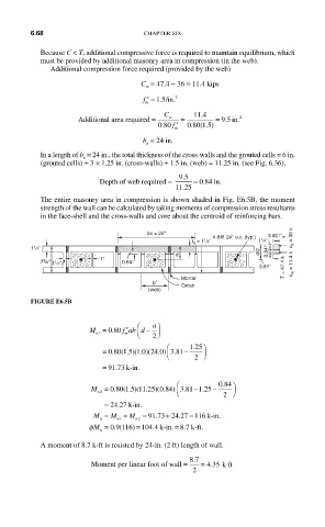
The entire masonry area in compression is shown shaded in Fig. E6.5B, the moment
strength of the wall can be calculated by taking moments of compression stress resultants
in the face-shell and the cross-walls and core about the centroid of reinforcing bars.
be = 24''
# 8@ 24'' o.c. (typ.) 3.80 f′ m c s = 36 k
t s = 1 1 /4'' 1 1 /4''
1 1 /4''
d d/2 0.84''
1''
7 5 /8'' 1 1 /4'' 0.84''
3.81'' T = 47.4 k c w = 11.4 k
Mortar
b′
Grout
(web)
FIGURE E6.5B
⎛ a ⎞
080 ′
⎜
M = . f ab d − ⎟
⎝
2 ⎠
m
n1
⎛ . 125 ⎞
. ⎜
.
)
(
(
.
(
.
)
.
)
= 080 15 10 240) 381− ⎟
⎝ 2 ⎠
= 91 .73 k-in.
⎛ 084 ⎞ ⎞
.
.
M = 080 15 1125 084) 381 125−
− .
.
(
(
)
(
.
)
.
.
n2 ⎝ 2 ⎠
.
= 24 27 k-in.
+
=
.
.
M = M + M = 91 73 24 27 116 k-inn.
n n 1 n 2
φM = 0 9 116) = 104 4 k-in. = 8 7. k-ft.
.
.(
n
A moment of 8.7 k-ft is resisted by 24-in. (2 ft) length of wall.
87 .
.
Moment per linear foot of wall = = 435 k-ft
2