
Page 421 - Design of Reinforced Masonry Structures
P. 421
6.72 CHAPTER SIX
Ties embedded
in mortar joints
Courses Courses Alternate Courses Courses
Alternate Alternate Alternate
No. 2 bars
bent in form
of U, greased
and spaced
16 × 20 16 × 16 16 in. O.C. 16 × 20 16 × 24
Ties embedded
in mortar joints
Courses Courses Courses
Alternate Alternate Alternate
16 × 16 16 × 20 16 × 24
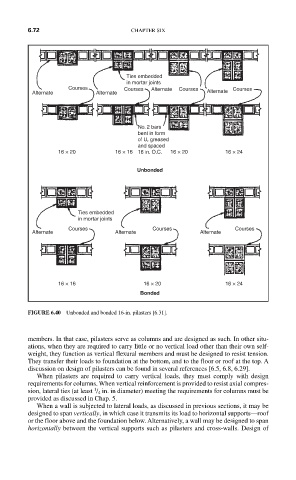
FIGURE 6.40 Unbonded and bonded 16-in. pilasters [6.31].
members. In that case, pilasters serve as columns and are designed as such. In other situ-
ations, when they are required to carry little or no vertical load other than their own self-
weight, they function as vertical flexural members and must be designed to resist tension.
They transfer their loads to foundation at the bottom, and to the floor or roof at the top. A
discussion on design of pilasters can be found in several references [6.5, 6.8, 6.29].
When pilasters are required to carry vertical loads, they must comply with design
requirements for columns. When vertical reinforcement is provided to resist axial compres-
1
sion, lateral ties (at least / 4 in. in diameter) meeting the requirements for columns must be
provided as discussed in Chap. 5.
When a wall is subjected to lateral loads, as discussed in previous sections, it may be
designed to span vertically, in which case it transmits its load to horizontal supports—roof
or the floor above and the foundation below. Alternatively, a wall may be designed to span
horizontally between the vertical supports such as pilasters and cross-walls. Design of