
Page 416 - Design of Reinforced Masonry Structures
P. 416
WALLS UNDER GRAVITY AND TRANSVERSE LOADS 6.67
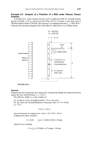
Example 6.5 Analysis of a T-Section of a Wall under Flexure: T-beam
Analysis.
A nominal 8-in.-wide concrete masonry wall is reinforced with No. 8 Grade 60 bars
placed vertically at 24 in. center-to-center (Fig. E6.5A). It carries a roof dead load of
2
400 lb/ft and live load of 250 lb/ft. The masonry is in running bond and ′ =f 1500 lb/in .
m
Calculate the moment strength of the wall which is subjected to out-of-plane loads.
D = 400 lb/ft
Lr = 250 lb/ft
e = 4"
Roof
Ledger beam
Lateral loads
Wind or
seismic # 8 @ 24" o.c.
vertical bars
h
Horizontal bars
8" nominal
CMU wall
FIGURE E6.5A
Solution
Estimate the area of masonry in compression. Assume that depth of compression block
equals the face-shell thickness, t = 1.25 in.
s
The effective width, b , is the smallest of
e
(a) Center-to-center of reinforcement = 24 in. (governs)
(b) Six times the nominal thickness of masonry unit = 6 × 8 = 48 in.
(c) 72 in.
Use b = 24 in.
e
Area of masonry in compression = bets = 24 (1.25) = 30 in. 2
Compression stress resultant:
′
C = 0 80. f ab = 0 80 1 5 30. ( . )( ) = 36 kips
m
Tensile force resultant,
T = A f = 0.79(60) = 47.4 kips > 36 kips
s y