
Page 138 - Design of Simple and Robust Process Plants
P. 138
4.2 The Methodology of Process Synthesis 123
± Placement of heat engines above the pinch and selection of the preferred uti-
lity levels. (Integration of heat engines across the pinch are counter-produc-
tive, as heat is transferred across the pinch.)
Care must be taken, as excess heat produced by steam engines at a certain steam
level (due to decreasing efficiencies) will be counter-productive, especially if it
results in excess at the lowest level and crosses the pinch.
. Reactor conditions are often dominant to integration due to its impact on
selectivity, conversion, and catalyst lifetime, if the options are available:
± Exothermic reactors are preferably placed above the pinch.
± Endothermic reactors are preferably placed below the pinch.
± Appropriately designed exothermic reactor sections/processes are, in princi-
ple, energy exporters.
± The location of the pinch point is subject to process modification and is not a
fixed point during the evaluation of several flowsheet options.
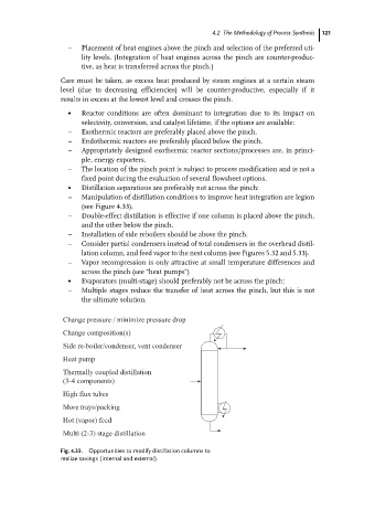
. Distillation separations are preferably not across the pinch:
± Manipulation of distillation conditions to improve heat integration are legion
(see Figure 4.33).
± Double-effect distillation is effective if one column is placed above the pinch,
and the other below the pinch.
± Installation of side reboilers should be above the pinch.
± Consider partial condensers instead of total condensers in the overhead distil-
lation column, and feed vapor to the next column (see Figures 5.32 and 5.33).
± Vapor recompression is only attractive at small temperature differences and
across the pinch (see ªheat pumpsº)
. Evaporators (multi-stage) should preferably not be across the pinch:
± Multiple stages reduce the transfer of heat across the pinch, but this is not
the ultimate solution.
Change pressure / minimize pressure drop
Change composition(s)
Side re-boiler/condenser, vent condenser
Heat pump
Thermally coupled distillation
(3-4 components)
High flux tubes
More trays/packing
Hot (vapor) feed
Multi (2-3) stage distillation
Fig. 4.33. Opportunities to modify distillation columns to
realize savings (internal and external).