
Page 192 - Digital Analysis of Remotely Sensed Imagery
P. 192
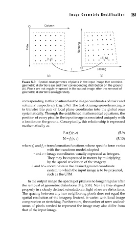
Image Geometric Rectification      157


                   O        Column


                   Row                          Northing


                             (r, c)                        (E, N)

                                                O
                                           f             Easting
                             (a)                           (b)
               FIGURE 5.9  Spatial arrangements of pixels in the input image that contains
               geometric distortions (a) and their corresponding distribution on the ground
               (b). Pixels are not regularly spaced in the output image after the removal of
               geometric distortions (exaggerated).


               corresponding to this position has the image coordinates of row r and
               column c, respectively (Fig. 5.9a). The task of image georeferencing is
               to transfer this pair of local plane coordinates into the global ones
               systematically. Through the established mathematical equations, the
               position of every pixel in the input image is associated uniquely with
               a location on the ground. Conceptually, this relationship is expressed
               mathematically as

                                      E = f (r, c)                   (5.9)
                                          1
                                      N = f (r, c)                  (5.10)
                                           2
               where f  and f  =  transformation functions whose specific form varies
                      1    2
                             with the transform model adopted
                      r and c =  image coordinates usually expressed as integers.
                             They may be expressed in meters by multiplying
                             by the spatial resolution of the imagery
                     E and N =  coordinates in the desired ground coordinate
                             system to which the input image is to be projected,
                             such as the UTM

                   In the output image the spacing of pixels is no longer regular after
               the removal of geometric distortions (Fig. 5.9b). Nor are they aligned
               properly in a clearly defined orientation in light of severe distortions.
               The spacing between any two neighboring pixels does not equal the
               spatial resolution of the imagery. Instead, it varies with local image
               compression or stretching. Furthermore, the number of rows and col-
               umns of pixels needed to represent the image may also differ from
               that of the input image.