
Page 166 - Distributed model predictive control for plant-wide systems
P. 166
140 Distributed Model Predictive Control for Plant-Wide Systems
Predictor 1 MPC 2 MPC 3 MPC n-2 Predictor n-1 Predictor n
u 2 u 3 u n-2
u →F 2 u →F 3 u n-2 →F n-2
3
2
x P1 P2 x P4
x
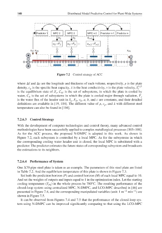
Figure 7.2 Control strategy of ACC
where Δl and Δz are the longitude and thickness of each volume, respectively, is the plate
(i, j)
density, c is the specific heat capacity, is the heat conductivity, v is the plate velocity, ̆x s
p
is the equilibrium state of S , C W is the set of subsystems, in which the plate is cooled by
s
water, C is the set of subsystems in which the plate is cooled major through radiation, F s
A
is the water flux of the header unit in S , F , v , a, b, and c are constants, and their detailed
0
s
0
definitions are available in [19, 104]. The different value of , c , and with different steel
p
temperature can also be found in [104].
7.2.6.3 Control Strategy
With the development of computer technologies and control theory, many advanced control
methodologies have been successfully applied to complex metallurgical processes [105–108].
As for the ACC process, the proposed N-DMPC is adopted in this work. As shown in
Figure 7.2, each subsystem is controlled by a local MPC. As for the subsystems in which
the corresponding cooling water header unit is closed, the local MPC is substituted with a
predictor. The predictor estimates the future states of corresponding subsystem and broadcasts
the estimations to its neighbors.
7.2.6.4 Performance of System
One X70 pipe steel plate is taken as an example. The parameters of this steel plate are listed
in Table 7.2. And the equilibrium temperature of this plate is shown in Figure 7.3.
Set both the prediction horizon (P) and control horizon (M) of each local MPC equal to 10.
And set the weights of outputs and inputs equal to 1 in the optimization index. Let the starting
◦
cooling temperature (T ) in the whole process be 780 C. The resulting performance of the
P2
closed-loop system using centralized MPC, N-DMPC, and LCO-MPC described in [46] are
−1
presented in Figure 7.4, and the corresponding manipulated variables (unit: 1 m −2 min )are
shown in Figure 7.5.
It can be observed from Figures 7.4 and 7.5 that the performance of the closed-loop sys-
tem using N-DMPC can be improved significantly comparing to that using the LCO-MPC