Page 291 - Distributed model predictive control for plant-wide systems
P. 291

High-Speed Train Control with Distributed Predictive Control           265


                         320           CRH1 Traction
                         300             CRH5 Traction
                       EMU Traction (kN), Resistance (kN)  220  CRH2-300  CRH3 Traction  CRH2-300
                         280
                         260
                         240

                         200
                         180
                                        Traction
                         160
                                                                 Resistance
                         140
                         120
                                 CRH2 Traction
                         100
                          80
                          60
                          40
                          20  CRH5 Resistance  CRH1 Resistance     CRH3
                                                                   Resistance
                                                 CRH1 Resistance
                           0
                             0  20  40  60  80  100  120  140  160  180  200  220  240  260  280  300  320  340
                                                          .  –1
                                             Train Speed (Km  h  )
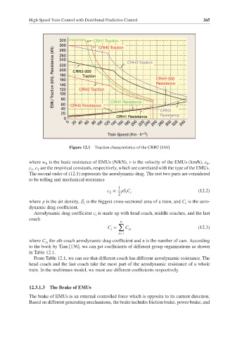
                             Figure 12.1  Traction characteristics of the CRH2 [140]


             where w is the basic resistance of EMUs (N/kN), v is the velocity of the EMUs (km/h), c ,
                    0                                                                 0
             c , c are the empirical constants, respectively, which are correlated with the type of the EMUs.
              1  2
             The second order of (12.1) represents the aerodynamic drag. The rest two parts are considered
             to be rolling and mechanical resistance
                                                 1
                                             c =     S C                          (12.2)
                                              2
                                                     i i
                                                 2
             where    is the air density, S is the biggest cross-sectional area of a train, and C is the aero-
                                                                             i
                                   i
             dynamic drag coefficient.
               Aerodynamic drag coefficient c is made up with head coach, middle coaches, and the last
                                        i
             coach
                                                  n
                                                 ∑
                                             C =    C                             (12.3)
                                              i       ix
                                                  x=1
             where C the xth coach aerodynamic drag coefficient and n is the number of cars. According
                    ix
             to the book by Tian [136], we can get coefficients of different group organizations as shown
             in Table 12.1.
               From Table 12.1, we can see that different coach has different aerodynamic resistance. The
             head coach and the last coach take the most part of the aerodynamic resistance of a whole
             train. In the multimass model, we must use different coefficients respectively.

             12.3.1.3  The Brake of EMUs
             The brake of EMUs is an external controlled force which is opposite to its current direction.
             Based on different generating mechanisms, the brake includes friction brake, power brake, and
   286   287   288   289   290   291   292   293   294   295   296