Page 295 - Distributed model predictive control for plant-wide systems
P. 295

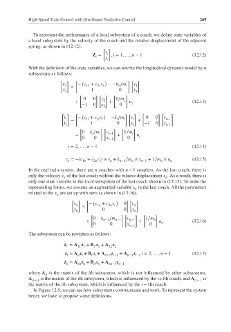
High-Speed Train Control with Distributed Predictive Control           269


               To represent the performance of a local subsystem of a coach, we define state variables of
             a local subsystem by the velocity of the coach and the relative displacement of the adjacent
             spring, as shown in (12.12):
                                            [ ]
                                             v
                                        Z =   i  , i = 1, … , n − 1              (12.12)
                                         i   x
                                              i
             With the definition of the state variables, we can rewrite the longitudinal dynamic model by n
             subsystems as follows:
                          [ ]   [ (          )        ][ ]
                           ̇ v 1  =  − c + c v  −k ∕m 1  v 1
                                                  1
                                          21 r
                                     11
                           ̇ x 1       1           0     x 1
                                  [      ][ ]   [     ]
                                    0   0  v     1∕m
                                +           2  +     1  u 1                      (12.13)
                                   −1   0  x       0
                                            2
                           [ ]  [ (         )        ][ ]   [      ][   ]
                            ̇ v i  =  − c + c v  −k ∕m i  v i  +  0  0  v i+1
                                         2i r
                                                  i
                                     1i
                            ̇ x i      1          0     x i  −1   0  x i+1
                                  [        ][   ]   [    ]
                                   0   k ∕m i  v i−1  1∕m i
                                       i
                                +                 +       u i
                                   0    0    x        0
                                              i−1
                             i = 2, … , n − 1                                    (12.14)
                             ̇ v =−(c + c v )× v + k  ∕m × x   + 1∕m × u         (12.15)
                             n     1n   2n r   n   n−1  n   n−1     n   n
             In the real train system, there are n coaches with n − 1 couplers. As the last coach, there is
             only the velocity v of the last coach without the relative displacement x . As a result, there is
                                                                      n
                            n
             only one state variable in the local subsystem of the last coach shown in (12.15). To unite the
             representing forms, we assume an augmented variable x in the last coach. All the parameters
                                                         n
             related to the x are set up with zero as shown in (12.16).
                         n
                               [ ]   [ (         )    ][ ]
                                ̇ v   − c + c v      0  v
                                 n  =     1n  2n r       n
                                ̇ x         0        0  x
                                 n                       n
                                       [            ][   ]   [    ]
                                        0  k n−1 ∕m n−1  v n−1  1∕m n
                                     +                     +       u n           (12.16)
                                        0      0      x n−1    0
             The subsystem can be rewritten as follows:
                            ̇ z = A z + B u + A z
                             1   11 1   1 1   12 2
                            ̇ z = A z + B u + A  z  + A  z  i = 2, … , n − 1     (12.17)
                             i   ii i  i i   ii+1 i+1  ii−1 i−1
                            ̇ z = A z + B u + A   z
                             n   nn n   n n   nn−1 n−1
             where A is the matrix of the ith subsystem, which is not influenced by other subsystems,
                    ii
             A ii + 1  is the matrix of the ith subsystem, which is influenced by the i+1th coach, and A ii − 1  is
             the matrix of the ith subsystem, which is influenced by the i − 1th coach.
               In Figure 12.5, we can see how subsystems communicate and work. To represent the system
             better, we have to propose some definitions.
   290   291   292   293   294   295   296   297   298   299   300