
Page 299 - Distributed model predictive control for plant-wide systems
P. 299
High-Speed Train Control with Distributed Predictive Control 273
V
F x2 F x3
F 21 F 12 F 32
F 23 F 43 F 34
W 01 W 02 W 03 W 04
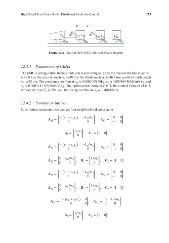
Figure 12.6 Half of the CRH2 EMUs schematic diagram
12.4.1 Parameters of CRH2
The EMU’s configuration in the simulation is according to [141]; the mass of the first coach m 1
is 42.8 ton, the second coach m is 48 ton, the third coach m is 46.5 ton, and the fourth coach
3
2
m is 42 ton. The resistance coefficient c is 0.8806 N/kN/kg, c is 0.007444 N/kN m/s kg, and
1
4
0
2 2
c is 0.0001143 N/kN m /s kg. The optimization horizon P is 4, the control horizon M is 2,
2
the sample time T is 20 s, and the spring coefficient k is 10488 kN/m.
s
i
12.4.2 Simulation Matrix
Substituting parameters we can get four neighborhood subsystems:
[ ( ) ] [ ]
− c + c v −k ∕m 0 0
A = 1 2 r 1 1 , A =
11 1 0 12 −1 0
[ ]
1∕m [ ]
B = 1 , C = 1 0
1 0 1
[ ( ) ] [ ]
− c + c v −k ∕m 2 0 0
1
1
2 r
A 22 = , A 23 =
1 0 −1 0
[ ] [ ]
0 k ∕m 2 1∕m 2 [ ]
1
A 21 = , B = , C = 1 0
2
2
0 0 0
[ ( ) ] [ ]
− c + c v −k ∕m 3 0 0
2 r
1
1
A 33 = , A 34 =
1 0 −1 0
[ ] [ ]
0 k ∕m 1∕m [ ]
A = 1 3 , B = 3 , C = 1 0
32 0 0 3 0 3
[ ( ) ] [ ]
− c + c v 0 0 k ∕m
A = 1 2 r , A = 1 4
44 0 0 43 0 0
[ ]
1∕m 4 [ ]
B = , C = 1 0
4
4
0