
Page 292 - Distributed model predictive control for plant-wide systems
P. 292
266 Distributed Model Predictive Control for Plant-Wide Systems
Table 12.1 Coefficients
Number 1 2 3 4
Coach 1 0.184 0.184 0.188 0.189
Coach 2 0.081 0.044 0.052 0.069
Coach 3 0.068 0.07 0.049 0.094
Coach 4 0.062 0.073 0.083 0.085
Coach 5 0.053 0.106 0.104 0.200
Coach 6 0.095 0.082 0.202
Coach 7 0.097 0.200
Coach 8 0.086
Coach 9 0.203
c = 0.929 c = 0.759 c = 0.678 c = 0.627
i i i i
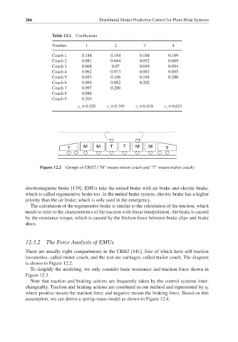
M M T T M M
T T
Figure 12.2 Groups of CRH2 (“M” means motor coach and “T” means trailer coach)
electromagnetic brake [139]. EMUs take the united brake with air brake and electric brake,
which is called regenerative brake too. In the united brake system, electric brake has a higher
priority than the air brake, which is only used in the emergency.
The calculation of the regenerative brake is similar to the calculation of the traction, which
needs to refer to the characteristics of the traction with linear interpolation. Air brake is caused
by the resistance torque, which is caused by the friction force between brake clips and brake
discs.
12.3.2 The Force Analysis of EMUs
There are usually eight compartments in the CRH2 [141], four of which have self-traction
locomotive, called motor coach, and the rest are carriages, called trailer coach. The diagram
is shown in Figure 12.2.
To simplify the modeling, we only consider basic resistance and traction force shown in
Figure 12.3.
Note that traction and braking actions are frequently taken by the control systems inter-
changeably. Traction and braking actions are combined in our method and represented by u i
where positive means the traction force and negative means the braking force. Based on this
assumption, we can derive a spring–mass model as shown in Figure 12.4.