Page 293 - Distributed model predictive control for plant-wide systems
P. 293

High-Speed Train Control with Distributed Predictive Control           267


                                                V


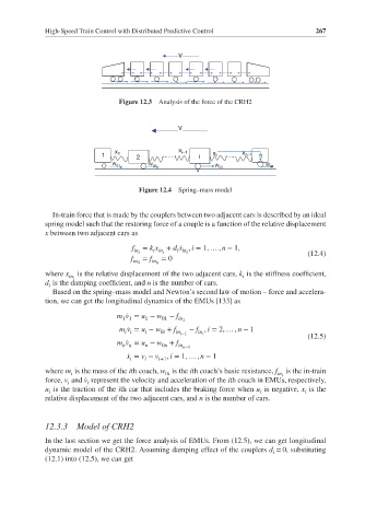
                                Figure 12.3  Analysis of the force of the CRH2


                                                V


                                                x i–1    x
                               x 1
                            1        2               i    i      x n–1  n
                               W 01     W 02                           W 04
                                                          W 03
                                      Figure 12.4  Spring–mass model


               In-train force that is made by the couplers between two adjacent cars is described by an ideal
             spring model such that the restoring force of a couple is a function of the relative displacement
             x between two adjacent cars as
                                    f  = k x  + d ̇x , i = 1, … , n − 1,
                                    in i  i in i  i in i                          (12.4)
                                    f  = f  = 0
                                    in 0  in n
             where x  is the relative displacement of the two adjacent cars, k is the stiffness coefficient,
                   in i                                          i
             d is the damping coefficient, and n is the number of cars.
              i
               Based on the spring–mass model and Newton’s second law of motion – force and accelera-
             tion, we can get the longitudinal dynamics of the EMUs [133] as

                                m ̇v = u − w − f in 1
                                 1 1
                                            01
                                       1
                                 m ̇v = u − w + f  − f , i = 2, … , n − 1
                                  i i  i   0i  in i−1  in i
                                                                                  (12.5)
                                m ̇v = u − w + f
                                 n n   n    0n  in n−1
                                   ̇ x = v − v i+1 , i = 1, … , n − 1
                                       i
                                   i
             where m is the mass of the ith coach, w is the ith coach’s basic resistance, f  is the in-train
                    i                        0i                           in i
             force, v and ̇v represent the velocity and acceleration of the ith coach in EMUs, respectively,
                   i    i
             u is the traction of the ith car that includes the braking force when u is negative, x is the
              i                                                       i          i
             relative displacement of the two adjacent cars, and n is the number of cars.
             12.3.3  Model of CRH2
             In the last section we get the force analysis of EMUs. From (12.5), we can get longitudinal
             dynamic model of the CRH2. Assuming damping effect of the couplers d = 0, substituting
                                                                         i
             (12.1) into (12.5), we can get
   288   289   290   291   292   293   294   295   296   297   298