
Page 364 - Dust Explosions in the Process Industries
P. 364
Propagation of Flames in Dust Clouds 333
dispersion system consists of a compressed-airreservoir of volume V, << V,, at an initial
pressure P2 >> P,. In some apparatuses, the dust is initially placed on the high-pressure
side of the dispersion air valve, as indicated in Figure 4.39; whereas in other apparatus,
it is placed downstream of the valve. Normally, the mass of dispersion air is not negligi-
ble compared with the initial mass of air in the main vessel. This causes a significantrise
of the pressure in the main vessel once the dispersionairhas been dischargedinto the main
vessel. In some investigations,this is compensated for by partial evacuation of the main
vessel prior to dispersion,so that the final pressure after dispersion completion,just prior
to ignition,is atmospheric.This is important if absolutedata are required,because the max-
imum explosionpressure for a given dust at a given concentration is approximately pro-
portional to the initial absolute air pressure. Both the absolute sizes of VI and V, and the
ratio between them vary substantially from apparatus to apparatus.The smallest VI used
are on the order of 1 liter, whereas the largest that has been traced is 250 m3.The design
of the dust dispersion system varies considerably from apparatus to apparatus.A number
of different nozzle types have been developed, with the aim to break up agglomeratesand
ensure homogeneous distribution of the dust in the main vessel. The ignition source has
also been a factor of considerablevariation. In some of the earlier investigations, contin-
uous sources like electric arcs or trains of electric sparks and glowingresistance wire coils
were used, but it has become common to use short-duration sources initiated at a given
time interval after opening of the dust dispersion valve. These sources vary from electric
sparks via exploding wires to various forms of electrically triggered chemical ignitors.
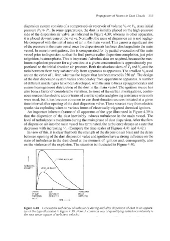
An important inherent feature of all apparatus of the type illustrated in Figure 4.39 is
that the dispersion of the dust inevitably induces turbulence in the main vessel. The
level of turbulence is maximum during the main phase of dust dispersion.After the flow
of dispersion air into the main vessel has terminated, the turbulence decays at a rate that
decreases with increasing VI. (Compare the time scales of Figures 4.41 and 4.42.)
In view of this, it is clear that both the strengthof the dispersion airblast and the delay
between opening of the dust dispersionvalue and ignitionhave a strong influence on the
state of turbulence in the dust cloud at the moment of ignition and, consequently, also
on the violence of the explosion. The situation is illustrated in Figure 4.40.
T STRONG AIR BLAST
TURBULENCE
INTENSITY WEAK AIR ELAS
OPENING DUST TURBULENCE
OF DUST DISPERSION DECAY
DISPERSION COMPLETED COMPLETED
VALVE
TIME-
Figure 4.40 Generation and decay of turbulence during and after dispersion of dust in an appara-
tus of the type illustrated in Figure 4.39. Note: A common way of quantifying turbulence intensity is
the root mean square of turbulent velocity.