
Page 476 - Dust Explosions in the Process Industries
P. 476
Sizing of Dust Explosion Vents 443
the curve for direct pneumatic injection is quite conservative. This kind of scatter, which
is also apparent in Figure 6.3, emphasizes the relevance of applying risk-analytical con-
siderations in vent sizing (see Section 6.6).
6.2.3
PNEUMATIC PIPELINE INJECTIONEXPERIMENTS
INVESSELS OF SMALL L/D
It was noted with considerable interest when the German-Swiss “school” of dust explo-
sion venting research started to use industrial pneumatic pipeline transport systems for
generating dust clouds even in vessels of small LID. Siwek (1989a, 1989b) discussed
a series of explosion experiments in which the dust clouds were generated in this way
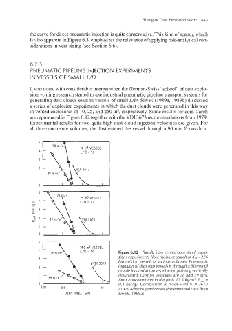
in vented enclosures of 10, 25, and 250 m3, respectively. Some results for corn starch
are reproduced in Figure 6.12 together with the VDI 3673 recommendations from 1979.
Experimental results for two quite high dust cloud injection velocities are given. For
all three enclosLire volumes, the dust entered the vessel through a 90 mm 0 nozzle at
Figure 6.12 Results from vented corn starch explo-
sions experiments (low-moisture starch of K,, = 226
bar m/s) in vessels of various volumes. Pneumatic
injection of dust into vessels is through a 90 mm 0
nozzle located at the vessel apex, pointing vertically
downward. Dust jet velocities are 78 and 39 m/s.
Dust concentration in the jet is 12.5 kg/m3, P,,,, =
0.1 bar(g). Comparison is made with VDI 3673
0.01 0.1 1 10 (I 979 edition) predictions (Experimental data from
VENT AREA [mZl Siwek, 1989a).