
Page 474 - Dust Explosions in the Process Industries
P. 474
Sizing of Dust Explosion Vents 44 1
1.5 I
SWITZERLAND
L/D = 6.25
VENT AREA = 0.5 m2
VENT AREA = 3.5 rn*
SILO HALF SILO
BOTTOM WAY UP ROOF
LOCATION OF IGNITION POINT IN SILO
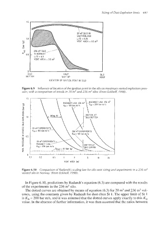
Figure 6.9 Influence of location of the ignition point in the silo on maximum vented explosions pres-
sure, with a comparison of trends in 20 m3 and 236 m3silos (From Eckhofi, 7990).
I I I I I Ill/ I I I I IIIII I
0.1 0.2 0.5 1 2 5 10 20
VENT AREA lml
Figure 6.10 Comparison of Radandt's scaling law for silo vent sizing and experiments in a 236 m3
vented silo in Norway (From Eckhoff, 1990).
In Figure 6.10, predictions by Radandt's equation (6.3) are compared with the results
of the experiments in the 236 m3 silo.
The dotted curves are obtained by means of equation (6.3) for 20 m3 and 236 m3vol-
umes, using the constants given by Radandt for dust class St 1. The upper limit of St 1
is Ks, = 200 bar ds, and it was assumed that the dotted curves apply exactly to this K,,
value. In the absence of further information, it was then assumed that the ratios between