
Page 478 - Dust Explosions in the Process Industries
P. 478
Sizing of Dust Explosion Vents 445
P5e
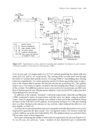
0 X1 Ignition source Cyclone vessel
0 PI-P7 Pressure transducers
T1 -T8 Light-sensing diodes
0 lgl-192 Ionization probes
VI -V2 Explosion venting doors v= 21ok
VcI--VC3 Vent covers for methane-
air explosion tests
Dust chamber
Figure 6.1 3 Experimental cyclone plant for studying dust explosion development under realistic
industrial condition (From Hayashi and Matsuda, 1988).
cross section and 3 m length ended in a 0.73 m3 cubical quenching box fitted with two
vents of 0.3 m2 and 0.1 m2, respectively. The venting of the cyclone itself was through
the 0.032 m2exhaust duct and the almost 10 m long 0.008 m2dust feeding duct. During
explosion experiments, two water-spraying nozzles for flame quenching were in opera-
tion in the exhaust duct to protect the fan just outside the quenching box. The ignition
source was a 5 kJ chemical igniter located in the dust feeding duct about 2 m upstream
of the cyclone. Two different polymer dusts were used in the experiments, an ABS resin
dust of median particle size 180pm and an ethylene-vinyl acetate (EVA) copolymer dust
of median particle size 40 pm.
In addition to the realistic “dynamic” explosion experiments, Hayashi and Matsuda
(1988) conducted a series of experiments with the same two dusts, using an artificial
“static” dust cloud generation method, very similar to that used in the experiments being
the basis of the VDI 3673 (1979 edition). As illustrated in Figure 6.14, the dust feeding
uct was then blocked at the entrance to the cyclone, which reduced the effective vent
area slightly, to 0.032 m2.
A system of two pressurized dust reservoirs and perforated tube dispersion nozzles were
employed to geneirate the dust clouds. The 5 kJ ignition source was located inside the
cyclone, halfway up on the axis (indicated by X2). The ignition source was activated about
BOO ms after onset of dust dispersion.
Envelopes embracing the results of both series of experiments are given in Figure 6.15.
As can be seen, the artificial, “static,” method of dust dispersion gave considerably