
Page 58 - Dust Explosions in the Process Industries
P. 58
Dust Explosions: An Overview 3 1
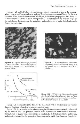
Figures 1.26 and 1.27 shows typical particle shapes in ground silicon in the compar-
atively coarse and fine particle size regions. The shapes are not very different for the two
fractions. Note that the size fraction, 37-53 ,um, is unable to propagate a dust flame. It
is necessary to add a tail of much finer particles. The influence of the detailed shape of
the particle size distribution on the ignitability and explosibility of metal dust clouds needs
further investigation.
Figure 1.26 Optical microscope picture of Figure 1.27 Scanning electron microscope
a metal-shadowed (shadowing angle 25" picture of fine fraction of ground silicon: typ-
with focal dane) 37-53 um fraction of ical Darticle size 2-3 um (Courtesv of W. C.
ground silicbn. Wedberg).
2000
>
'si 1500
9
2
-= 1000
c
0
\
%
500 . SILICON (CMIJ
Figure 1.28 (dP/dt),,, in Hartmann bomb of
DRY PROTEIN Kill1 clouds in air silicon dust, aluminum dust, and dust
0
0 5 10 15 20 25 from natural organic materials, as functions of par-
MEDIAN OR AVERAGE PARTICLE SIZE [urn] ticle size (From Eckhoff et al., 1986).
Figure 1.28 summarizes some data for the maximum rate of pressure rise for various
dusts as functions of median or average particle size.
Figure 1.29 illustrates how the minimum explosible dust concentration is influenced
by the particle size. The particles used in these experiments were close to monodis-
perse, that is, of narrow size distributions. In practice, the distributions may be quite wide,
and simple relationships for monosized dusts may not be valid. Hertzberg and Cashdollar