
Page 385 - Dynamics of Mechanical Systems
P. 385
0593_C11_fm Page 366 Monday, May 6, 2002 2:59 PM
366 Dynamics of Mechanical Systems
T n θ
n
k y
k
n m
r
mg x n x
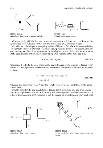
FIGURE 11.5.5 FIGURE 11.5.6
A free-body diagram of the pendulum bob. A simple mass–spring system.
Observe in Eq. (11.5.9) that the constraint tension force T does not contribute to the
generalized force. Observe further that the dimensions of F are force–length.
θ
Consider next the simple mass–spring system of Figure 11.5.6, where the mass m sliding
on a smooth surface is attached to a linear spring with modulus k. This system also has
only one degree of freedom represented by the displacement x of the mass away from its
static equilibrium position. The velocity and partial velocity of the mass are then:
v = ˙ x n and v = n (11.5.10)
x ˙ x x
Consider a free-body diagram showing the applied forces on the mass as in Figure 11.5.7
where N is the equivalent normal force of the surface. The generalized force on the mass
is then:
−
⋅
⋅
⋅
F =− kxn v ˙ x + Nnv ˙ x mgnv ˙ x
y
y
x
x
(11.5.11)
=− kx + −
00
Observe that the normal force N and the weight force mg do not contribute to the gener-
alized force.
Finally, consider the rod pendulum of Figure 11.5.8 consisting of a rod B of length
and mass m pinned at one end and moving in a vertical plane. Let B also be attached to
a linear torsion spring with modulus k. Let the spring be a “restoring spring” such that
k
O
mg n z
n y θ
G
B
kx n
n x
N
n
r
FIGURE 11.5.7 FIGURE 11.5.8
A free-body diagram of the mass. A rod pendulum with linear torsion restoring
spring.