
Page 430 - Dynamics of Mechanical Systems
P. 430
0593_C11_fm Page 411 Monday, May 6, 2002 2:59 PM
Generalized Dynamics: Kinematics and Kinetics 411
this system has one degree of freedom, which may be represented by the angle φ. Deter-
mine the generalized inertia force F θ * .
P11.9.8: See Problem P11.6.8. Consider again the rotating disk in the shaft-supported yoke
of Problem P11.6.8 and as shown again in Figure P11.9.8. With the angular speed of the
disk being specified, the system has two degrees of freedom, represented by the angles α
and β. Following the solution outline of Problem P11.6.8, determine the generalized inertia
*
forces F and F β * .
α
FIGURE P11.9.8
A disk spinning in a free-turning
yoke and supported by a shaft S.
Section 11.11 Potential Energy
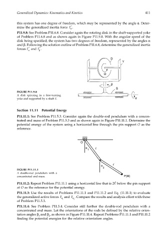
P11.11.1: See Problem P11.5.3. Consider again the double-rod pendulum with a concen-
trated end mass of Problem P11.5.3 and as shown again in Figure P11.11.1. Determine the
potential energy of the system using a horizontal line through the pin support O as the
reference.
O
θ
1
θ
2
FIGURE P11.11.1
A double-rod pendulum with a
concentrated end mass. P(M)
P11.11.2: Repeat Problem P11.11.1 using a horizontal line that is 2 below the pin support
at O as the reference for the potential energy.
P11.11.3: Use the results of Problems P11.11.1 and P11.11.2 and Eq. (11.11.1) to evaluate
the generalized active forces F and F . Compare the results and analysis effort with those
θ 1 θ 2
of Problem P11.5.3.
P11.11.4: See Problem P11.5.4. Consider still further the double-rod pendulum with a
concentrated end mass. Let the orientations of the rods be defined by the relative orien-
tation angles β and β , as shown in Figure P11.11.4. Repeat Problems P11.11.1 and P11.11.2
1
2
finding the potential energies for the relative orientation angles.