
Page 426 - Dynamics of Mechanical Systems
P. 426
0593_C11_fm Page 407 Monday, May 6, 2002 2:59 PM
Generalized Dynamics: Kinematics and Kinetics 407
F
4
F 5
F 2 F 3 12 ft
F 6 F 7
3 ft
K
O F n 3
F 4 ft O 8
1 K n
2
n 1
(A) (B)
FIGURE P11.5.9
(A) An elongated box kite. (B) A modeling and representation of turbulent wind forces on a box kite.
Section 11.6 Generalized Forces: Gravity and Spring Forces
P11.6.1: Consider again the triple-rod pendulum with a concentrated end mass of Problem
P11.5.5 and as shown again in Figure P11.6.1. As before, let the rods be identical with each
having length and mass m. Let G , G , and G be the mass centers of the rods. Let the
1
3
2
orientations of the rods be defined by the angles θ , θ , and θ shown in Figure P11.6.1.
2
3
1
Finally, let L be a reference level passing through the upper support pin at O.
a. Let h , h , h , and h measure the elevation of G , G , G , and P above L. (Observe
p
3
3
1
2
2
1
that h , h , h , and h are negative in the configuration shown in Figure P11.6.1.)
p
3
2
1
Determine h , h , h , and h in terms of θ , θ , and θ .
1
p
1
3
2
2
3
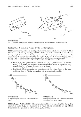
b. Use Eq. (11.6.5) to determine the contribution of the weight forces of the rods
and the weight of P to the generalized active forces F , F , and F .
θ 1 θ 2 θ 3
O L O L
θ β
1 1
G
1
θ
2
G β
2 2
θ 3 β
G 3
3
P(M) P(M)
FIGURE P11.6.1 FIGURE P11.6.2
A triple-rod pendulum with concentrated end A triple-rod pendulum with concentrated end mass
mass. with relative orientation angles.
P11.6.2: Repeat Problem P11.6.1 if the orientations of the rods are defined by the relative
orientation angles β , β , and β , as shown in Figure P11.6.2. Specifically, use Eq. (11.6.5)
1
3
2
to determine the generalized active forces F , F , and F .
β 1 β 2 β 3