
Page 456 - Dynamics of Mechanical Systems
P. 456
0593_C12_fm Page 437 Monday, May 6, 2002 3:11 PM
Generalized Dynamics: Kane’s Equations and Lagrange’s Equations 437
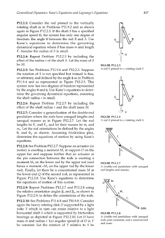
P12.2.3: Consider the rod pinned to the vertically
rotating shaft as in Problems P11.9.2 and as shown
again in Figure P12.2.3. If the shaft S has a specified
angular speed Ω, the system has only one degree of θ
freedom: the angle θ between the rod B and S. Use S B
Kane’s equations to determine the governing
dynamical equation where B has mass m and length
. Assume the radius of S is small.
Ω
P12.2.4: Repeat Problem P12.2.3 by including the
effect of the radius r of the shaft S. Let the mass of S
be M. FIGURE P12.2.3
P12.2.5: See Problems P11.9.4 and P12.2.3. Suppose A rod B pinned to a rotating shaft S
the rotation of S is not specified but instead is free,
or arbitrary, and defined by the angle φ as in Problem
P11.9.4 and as represented in Figure P12.2.5. This
system now has two degrees of freedom represented
by the angles θ and φ. Use Kane’s equations to deter-
mine the governing dynamical equations, assuming θ
the shaft radius r is small. S B
P12.2.6: Repeat Problem P12.2.5 by including the
effect of the shaft radius r and the shaft mass M.
P12.2.7: Consider a generalization of the double-rod φ
pendulum where the rods have unequal lengths and FIGURE P12.2.5
unequal masses as in Figure P12.2.7. Let the rod A rod B pinned to a rotating shaft S.
lengths be and , and let their masses be m and
1
2
1
m . Let the rod orientations be defined by the angles
2
θ and θ , as shown. Assuming frictionless pins, O
2
1
determine the equations of motion by using Kane’s θ 1 1
equations.
P12.2.8: See Problem P12.2.7. Suppose an actuator (or
θ
motor) is exerting a moment M at support O on the 2 2
1
upper bar and suppose further that an actuator at
the pin connection between the rods is exerting a
moment M on the lower rod by the upper rod (and FIGURE P12.2.7
2
hence a moment –M on the upper rod by the lower A double-rod pendulum with unequal
2
rod). Finally, let there be a concentrated mass M at rod lengths and masses.
the lower end Q of the second rod, as represented in
Figure P12.2.8. Use Kane’s equations to determine
the equations of motion of this system. O M 1
P12.2.9: Repeat Problems P12.2.7 and P12.2.8 using θ 1 1
the relative orientation angles β and β , as shown in M 2
2
1
Figure P12.2.9, to define the orientations of the rods.
2
θ
P12.2.10: See Problems P11.6.8 and P11.9.8. Consider 2
again the heavy rotating disk D supported by a light
yoke Y which in turn can rotate relative to a light Q(M)
horizontal shaft S which is supported by frictionless FIGURE P12.2.8
bearings as depicted in Figure P12.2.10. Let D have A double-rod pendulum with unequal
mass m and radius r. Let angular speed Ω of D in Y rods, joint moments, and a concentrated
be constant. Let the rotation of Y relative to S be end mass.